
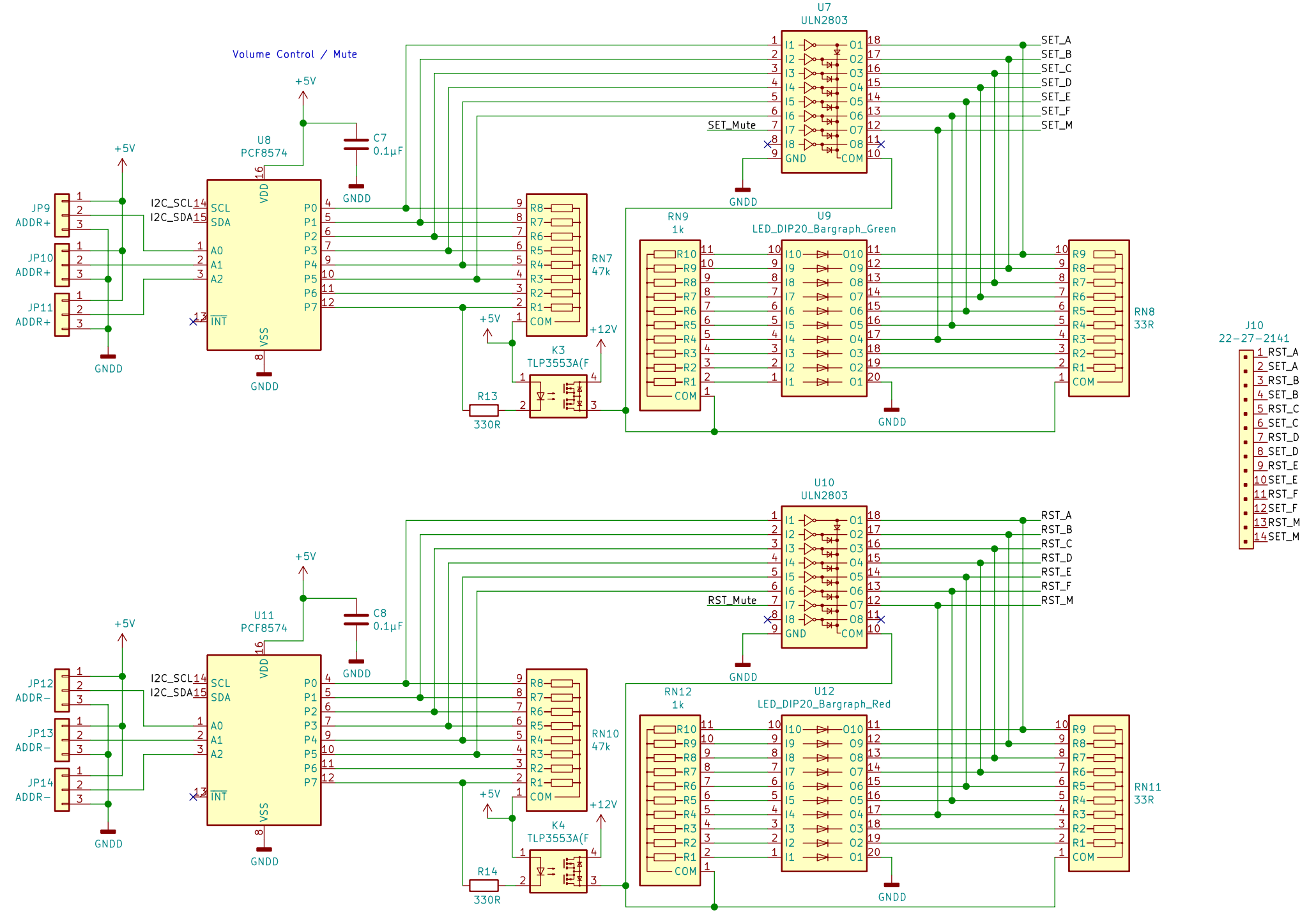
They are latching relays, so in steady state no current passes through their coils. When the volume or input is changed, then a 'set' or 'reset' current pulse gets routed to the relays in question.
This is the circuit controlling volume - and this one works fine. When the system has power applied, the software initialises all the PCF8574's ports P0 to P7 to low, from their initial state of high. So in steady state, the relays have +12V on both sides of the coil, with low having been inverted by the ULN2803. If a change in volume is made, then one or more of P0 thru P7 on U2 and U5 will momentarily 'pulse' high, pulling the voltage to zero on the appropriate side of the coil and operating the relay. The bargraph LEDs U3 and U6 are a telltale for when this current flows.
So - this one works:
This one, however, doesn't:
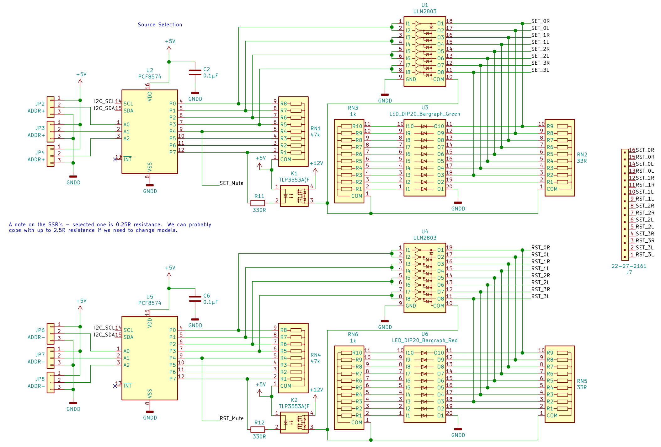
This controls the input selection. Now with it being a balanced linestage, two relays are needed for each channel. With there only being four inputs, I figured it made more sense to use all of the ULN2803 to still have one darlington array per coil, so I paralleled it on the TTS side (see U1 and U4, pins 1 thru 8. The idea being that when P0 pulses high, two relays are activated, one for each channel.
Unfortunately I don't get any LED activity at all from U3 and U6, aside from the 'power' LED (pins 1 to 20). The 12V supply also powers a series of front panel illumination LEDs, and they momentarily dim during the pulse, which seems to suggest that a big load is being put on the 12V supply every time any of P0 thru P7 goes high.
Given that this circuit is near-identical to the one for volume, I can only think that the paralleling of the ULN2803 input pins is responsible and somehow causing a short, but I cannot fathom out how or why. The relay coils are not connected at this point. I tried to model it in Spice to prove one way or the other but didn't have a lot of success there either (I'll talk about that separately if needed), so I'm having to fall back on the Audio Talk hive mind.
I'm pretty sure the ULN2803 can handle two relay coils in parallel per output so the fix is easy enough, but if I'm going to have to go through the hassle and expense of redesigning and remanufacturing the PCB, I want to be sure of the root cause first. Basically, did I make a dumb mistake with the ULN2803 wiring?
This is a PDF of the complete PCB which might be easier to read than the jpegs - https://user.fm/files/v2-242081f2a53cf9 ... Driver.pdf


