Page 4 of 5
#46 Re: AMB linestage rebuild
Posted: Wed Jan 11, 2023 5:44 pm
by Thermionic Idler
Nick wrote: ↑Tue Jan 10, 2023 10:06 pm
Did you not try my suggestion of changing the value of the pull up resistors? I still think 47k is wrong even in the case of single input single output. Would/might have avoided a new board.
I have not, but there was a genuine reason for that - I can't get my side cutters in, the resistor networks are simply packed too close to other components on the board for me to be able to snip them off.
I will look further into this though, before the re-do, and ask a question on the AMB forum about why 47k was picked - I do know that Ti Kan and Brian of Linuxworks spent some considerable effort refining this design empirically to work reliably, and so they must have arrived at that value for a reason. And I've had that driver circuit in place and working on AMB-issued PCB's for years and it's been flawless - the only issues originated from the Arduino and those were my fault.
The approach I've tried to take is only change what needs to be changed and don't second guess anything, cos these guys know a lot more about this stuff than I do! Look what happened when I deviated from the design and tried to connect one TTL to two darlingtons.
#47 Re: AMB linestage rebuild
Posted: Wed Jan 11, 2023 5:47 pm
by Thermionic Idler
Nick wrote: ↑Tue Jan 10, 2023 10:07 pm
Added in-line voltage drop resistor to connection for power relay which has a 12V coil
I would have been tempted to use a 3v3 zener.
See this kind of thing Nick is why you are a proper electronics engineer and I am a mere bumbling amateur. I haven't actually bought the part yet, I guess I just put the zener in where the resistor would go and hey presto - voltage dropped without the power loss.
#48 Re: AMB linestage rebuild
Posted: Wed Jan 11, 2023 6:45 pm
by andrew Ivimey
Yep that's a thought I've had a few times too - not about you, of course but Nick has a few tricks up his sleeve which do seem to hit the spot. Me, I'm all bias, intrigue, intuition, cynicism and a little experience - this doesn't always get me to where I want to be.
#49 Re: AMB linestage rebuild
Posted: Wed Jan 11, 2023 6:57 pm
by Nick
Well, you are still dropping the power as there is current and voltage, so P = I.E, but the big thing for me is that the voltage drop is independent of current.
#50 Re: AMB linestage rebuild
Posted: Wed Jan 11, 2023 7:19 pm
by Nick
Thermionic Idler wrote: ↑Wed Jan 11, 2023 5:44 pm
Nick wrote: ↑Tue Jan 10, 2023 10:06 pm
Did you not try my suggestion of changing the value of the pull up resistors? I still think 47k is wrong even in the case of single input single output. Would/might have avoided a new board.
I have not, but there was a genuine reason for that - I can't get my side cutters in, the resistor networks are simply packed too close to other components on the board for me to be able to snip them off.
I will look further into this though, before the re-do, and ask a question on the AMB forum about why 47k was picked - I do know that Ti Kan and Brian of Linuxworks spent some considerable effort refining this design empirically to work reliably, and so they must have arrived at that value for a reason. And I've had that driver circuit in place and working on AMB-issued PCB's for years and it's been flawless - the only issues originated from the Arduino and those were my fault.
The approach I've tried to take is only change what needs to be changed and don't second guess anything, cos these guys know a lot more about this stuff than I do! Look what happened when I deviated from the design and tried to connect one TTL to two darlingtons.
I would ave just soldered the four resistors on the back of the PCB leaving the 47k resistors in place. Adding 1k or 2k2 or 4k7 in parallel with 47k is as close to be good enough. That would be good enough to get the four lines workign or at least see if I was talking tosh.
My thoughts as to the size used are based on the spec sheet, the input current is specified as 0.93ma. So just being very sloppy, a 4k7 pull up would give
( 5v - 1.2v ) / ( 4k7 + 2k7 ) = 0.5ma
1k pull up would be
(5 - 1.2) / ( 1k + 2k7 ) = 1ma
The 1.2v is the two forward biased junctions in the darlington. The 2k7 the internal resistor.
The 47k they have specified would give
(5 - 1.2) / (47k + 2k7) = 76ua it seems to me, when you add the 100ua that seems to be in the most the PCF8574 can source, that gives you at most 0.18ma. Use that .18ma and that looks like it would give at most 100ma collector current on the output. Probably enough to drive the relay but its all a bit close to the edge IMHO.
#51 Re: AMB linestage rebuild
Posted: Thu Jan 12, 2023 9:04 am
by Thermionic Idler
Nick wrote: ↑Wed Jan 11, 2023 7:19 pm
I would ave just soldered the four resistors on the back of the PCB leaving the 47k resistors in place. Adding 1k or 2k2 or 4k7 in parallel with 47k is as close to be good enough. That would be good enough to get the four lines workign or at least see if I was talking tosh.
I didn't think of that either. Even just on one leg as a proof of concept, easy enough to do. I'll try that Saturday morning or if I get a moment before.
Thanks for the calculation Nick - I'll take that across to AMB and see what they say, it makes sense to me. BTW the relay coils are 16.7mA at the most (for two 12v coils in parallel), the standard-issue boards use 4.5V relays which draw a bit more, but they don't come anywhere near 100mA, so I guess that's why it works with 47k. I pondered whether it was to avoid excessive current leakage as all ports are at low, but it's only 1mA per port with a 4k7 so....???
#52 Re: AMB linestage rebuild
Posted: Thu Jan 12, 2023 9:41 am
by Nick
Yep, but in your case at the moment, remember you also have the extra current from the relay "pull up" resistors.
#53 Re: AMB linestage rebuild
Posted: Thu Jan 12, 2023 1:13 pm
by Thermionic Idler
Indeed, looks like I forgot about that a second time!
I've asked the question. There is one reason I can think of which I included in my post - the system is designed to support up to 4 relay boards with two port expanders on each one, so that's potentially 8 PCF8574's, all of which have their ports at low in 'steady state'. So 4k7 pullup resistors would result in an extra 64mA of current draw on the 5V power supply, which might make a difference if it was being fed by a wimpy transformer, and the majority of implementations have the relays driven from the same 5V supply. Go up to 47k and it becomes a tenth of that, obviously.
#54 Re: AMB linestage rebuild
Posted: Thu Jan 12, 2023 2:24 pm
by Nick
A very wimpy transformer indeed. But as you found 47k is just too much IMHO.
#55 Re: AMB linestage rebuild
Posted: Fri Jan 13, 2023 9:17 am
by Thermionic Idler
Well here's the reply I got...
Each "gate" in the ULN2803A is a darlington pair that has a Hfe of around 1000. It needs to pass 22mA at its output (collector) which is the rated coil current of the relay. Add about 3mA for the LED makes it 25mA. So the input (base) current into the darlington only needs to be 25uA. There is PLENTY of headroom for the PCF8574 to provide that, with the 47KΩ pull-up.
I've gone back and questioned that because (as I've done twice) he seems to have forgotton about the other half of the current limit pair that isn't in series with the relay coil, in this case that's 47R. I make the total draw for the standard 5V implementation 131mA, which still seems to be within the capabilities of the system as it does work, and work reliably.
Nevertheless, Nick, with the new board I see no reason not to take your advice and drop that pullup value, about 10k seems like a good compromise to me. That'll increase the 'headroom' whilst the current draw with 12V relays and a 15V rail will in fact be less than it is with the 5V implementation (even on the side with two relay coils in parallel, which I calculated to be 91.7mA). Whilst also limiting the leakage from having all the ports at zero, to 16mA.
#56 Re: AMB linestage rebuild
Posted: Fri Jan 13, 2023 11:03 am
by Nick
Yep, must be just me then that wants digital circuits to actually switch rather than just pass enough current

And just to be super picky, the 1000 gain is only for the UL2801, the 2k7 on the input of the 2803 will make the gain closer to 800. So with the 131ma you need, that's 163ua on the input. 100ua from the CCS in the PCF8574 (which is clearly only there to tie the output, they expect the pull up resistor to do the heavy lifting). 5v across 47k gives you 10ua, so 110 < 163, so I would say its not a good bit of design IMHO.
Not that the 5v is across the 47k is correct, assuming 1.2v for the two PN junctions in the darlington, that means its 3.8v across 47k + 2k7 so 7.7ua.
Using their argument if it was all clearly thought out and justified, why are they bothering with the pull up at all?
#57 Re: AMB linestage rebuild
Posted: Fri Jan 13, 2023 4:14 pm
by Thermionic Idler
Nick wrote: ↑Fri Jan 13, 2023 11:03 am
5v across 47k gives you 10ua, so 110 < 163, so I would say its not a good bit of design IMHO.
Not that the 5v is across the 47k is correct, assuming 1.2v for the two PN junctions in the darlington, that means its 3.8v across 47k + 2k7 so 7.7ua.
Have you missed a decimal point there - I make those numbers x10, so 106.3uA / 76.46uA.
#58 Re: AMB linestage rebuild
Posted: Fri Jan 13, 2023 4:18 pm
by Nick
Yes, you are right, my mistake.
#59 Re: AMB linestage rebuild
Posted: Fri Jan 13, 2023 4:43 pm
by Thermionic Idler
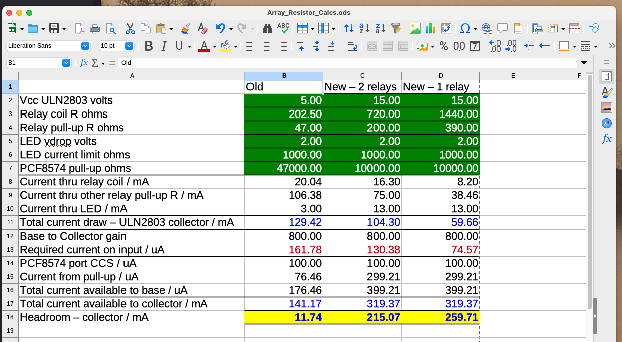
I just did a quick spreadsheet based on those calculations, putting the numbers in for the standard issue boards and comparing the results with my modified setup and 10k pull-ups.
So yes - the standard setup will (and does) work, with a whopping 11mA headroom on the output, by my calculations. And that would explain why the LED bargraphs didn't seem to light up very brightly.
With 10k pullups we get > 200mA headroom. The 2 relay / 1 relay column is where I'm connecting two relays in parallel to one darlington versus 1 relay.
EDIT - I think I may make the pullups on the 2-relay circuits 8.2k, that way the headroom becomes about the same on both circuits.
#60 Re: AMB linestage rebuild
Posted: Sat Jan 14, 2023 11:51 am
by Thermionic Idler
I got some further feedback from AMB which goes some way to explain why the thing works reliably with 47k pull-ups, (but I'm still resizing them on the new board).
Yes, you're right. I forgot about the effect of R2 which is effectively in parallel with the relay coil in series with the R2 on the opposite side. It does increase the collector current through the darlington, therefore increasing the base drive current to 0.13mA or so. While under static conditions the PCF8574 is rated to source only 100uA (max 300uA), the 47K external pull-up helps it. But more significantly, when being driven "high", the PCF8574's port will kick in an an extra internal "accelerator" strong pull-up for a brief amount of time (see the NXP PCF8574 datasheet). This is what gives it the extra headroom - since the relays are latching type, we only drive the port to high (or low) in a pulse to make the relay latch on a different state, and the PCF8574 accelerator feature is enough to make the latch happen reliably. This is is contrast to non-latching relays where we need to hold the port to a high (or low) state for an indefinite amount of time.