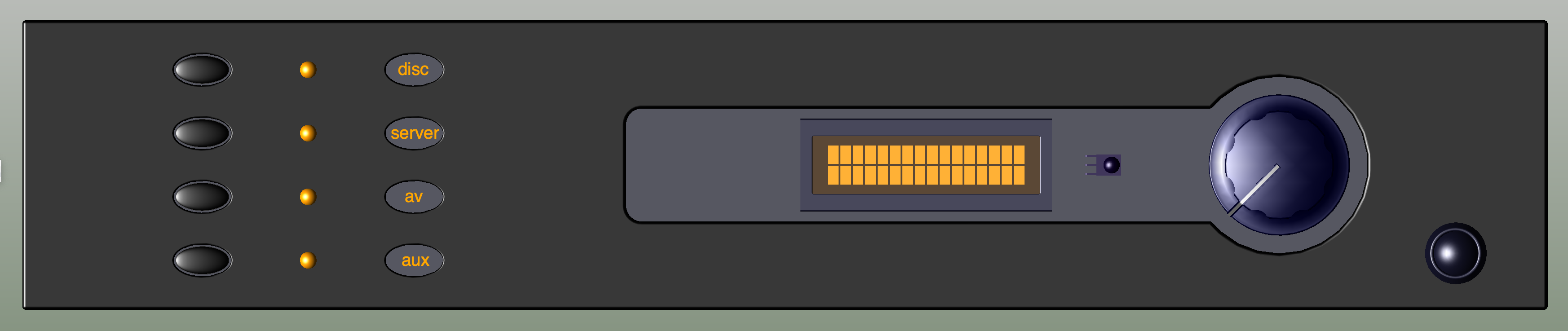
I'll come back to the front panel design later.
In order to use my existing LCDuino infrastructure successfully, I needed to confirm my understanding of how they implemented their stepped relay attenuator, and then check that the same control system would function properly with the new circuit. I know that people cleverer than me could probably have worked it out but I wanted to prove it in Spice. Here's how I did it.
Based on a six relay control, the first thing I had to do was set up the relay triggers for a binary count from 000000 to 111111, to simulate the output from the control system. The expected result would be the volume either decreasing from max to min, or the reverse. Easy to do, just a matter of doubling the period from least to most significant bit:
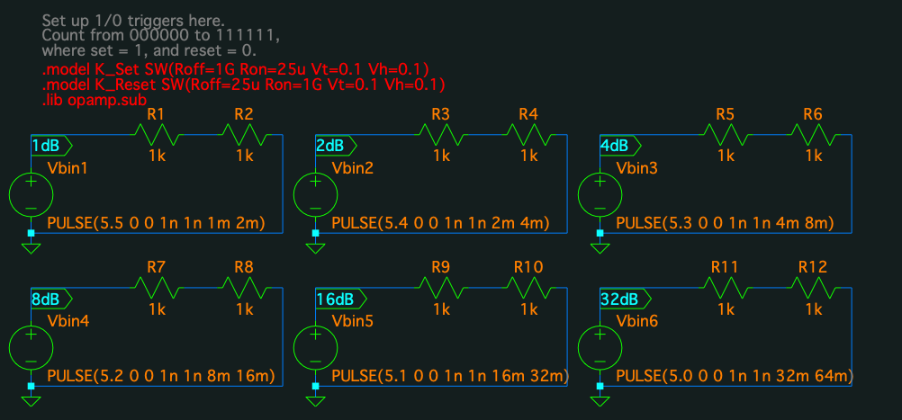
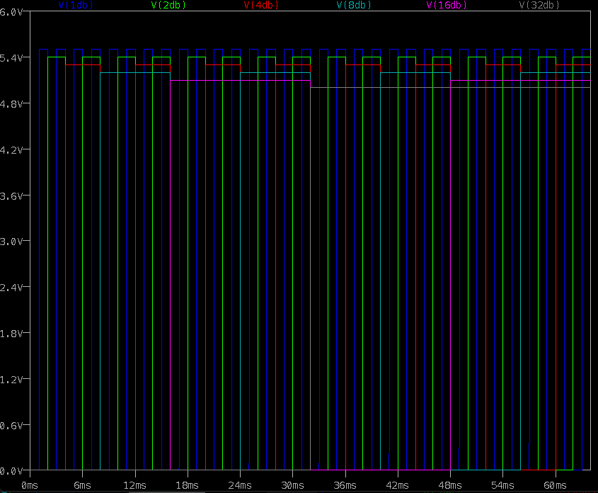
The output voltages were made slightly different to make it easier to read the sim results, this confirmed I'd set up the triggers correctly. You can see that at 0ms, all triggers are low, and at 63ms all are high:
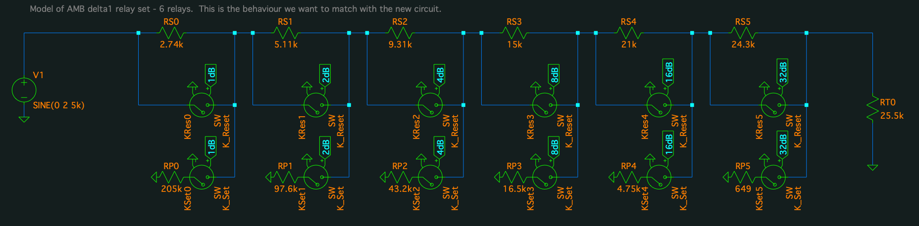
So, now we go to AMB's
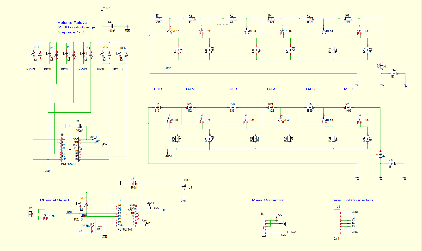
resistor value calculator, get the values for 6 relays, and copy the delta1 attenuator board schematic into Spice, making sure that Set and Reset are the right way round as that determines the volume direction. (LCDuino uses latching relays).
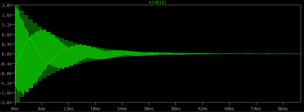
Run the sim, and looking at the voltage across RT0, we see a logarithmic volume descent:
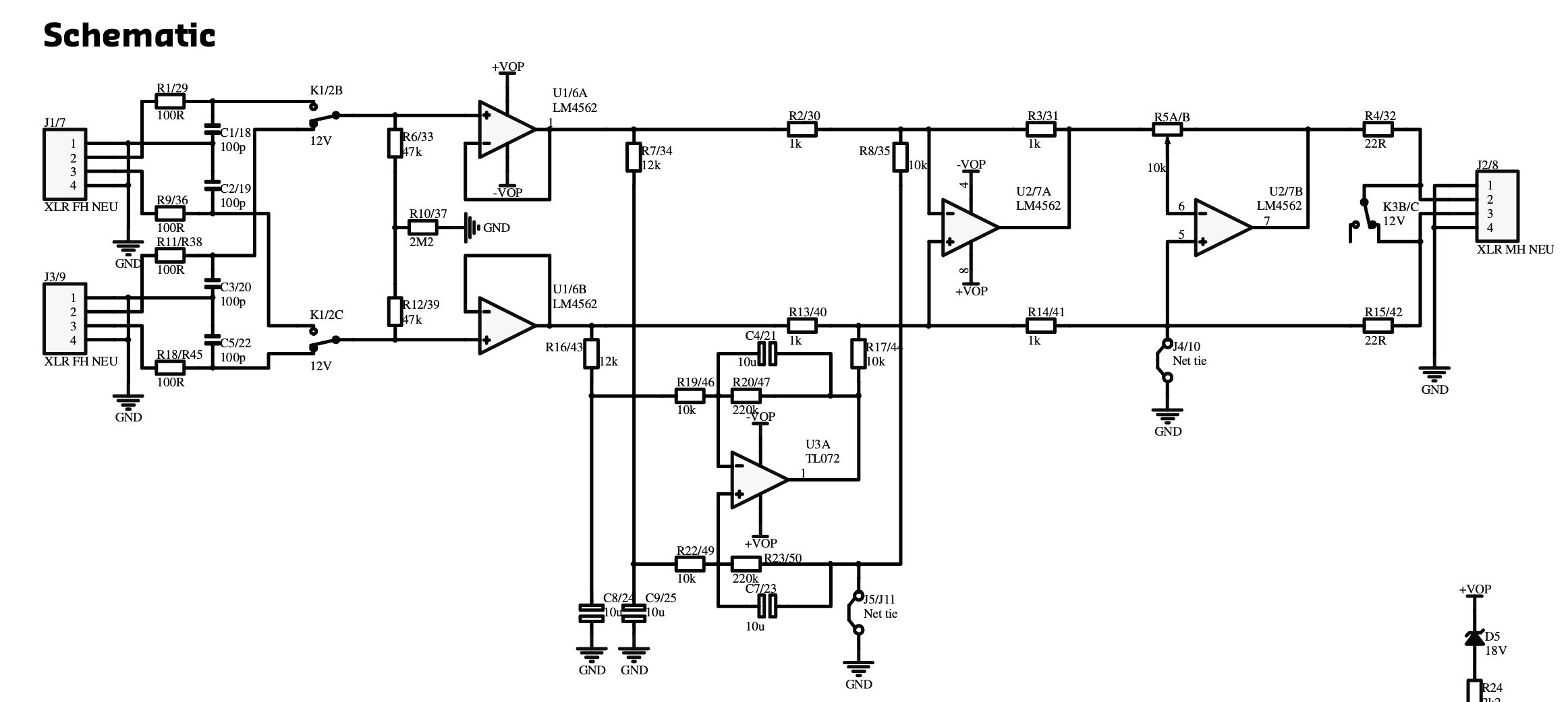
So what we want to do now, is hang the new circuit around the same 6 relays and check that we get the same result. To recap, Bruno Putzey's circuit is
at the foot of this article and here's
Hans Polak's switched relay modification. He since came up with a subsequent
6 relay design based on the same principles, and that is what I've decided to go ahead with as I would still like to retain a few dB's of gain at the preamp stage. The previous configuration I was investigating would have resulted in a unity gain stage.
So we first copy the Hans Polak schematic into Spice using the same relay set, followed by the Bruno Putzey linestage (I didn't bother with the 'dc servo' bit). Notice how much lower in value all the resistors are compared with a conventional attenuator:
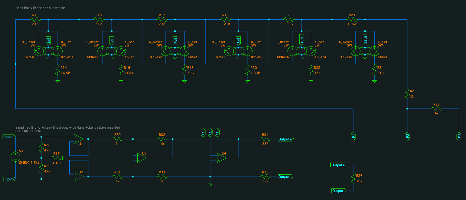
And we check the output...
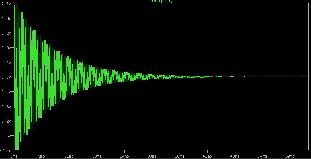
And there is a match with the AMB attenuator, confirming that if the same latching relays are used, connected per the Spice sim, and interfaced to LCDuino correctly, everything should work perfectly.
When I originally modelled the Hans Polak circuit, I had Set and Reset the wrong way round, so I got a volume increase instead of a decrease.
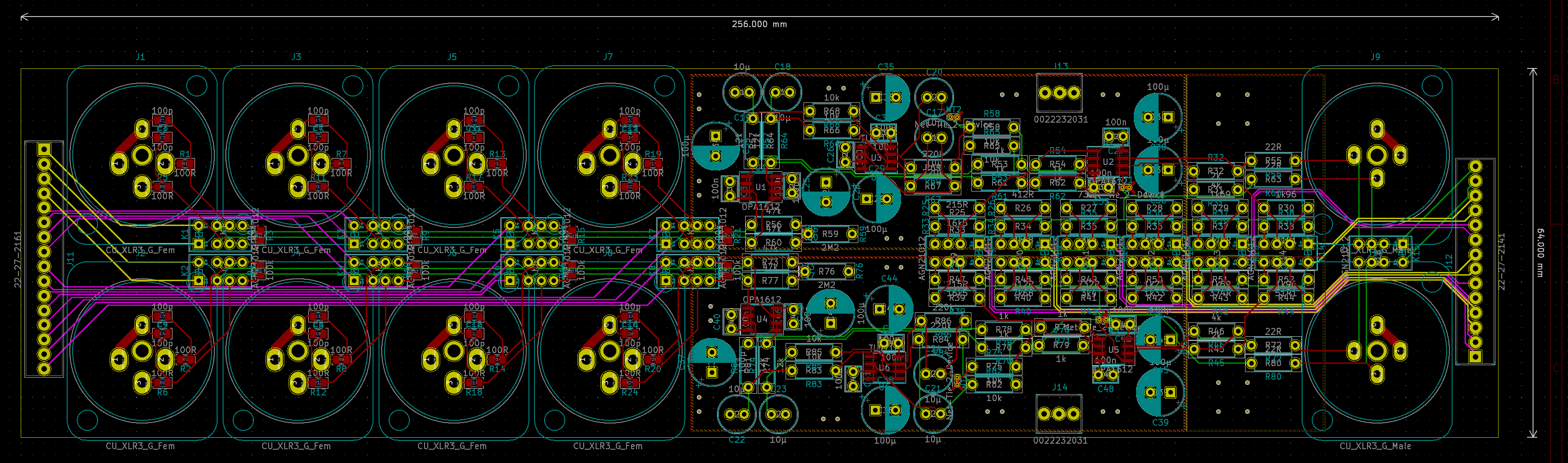
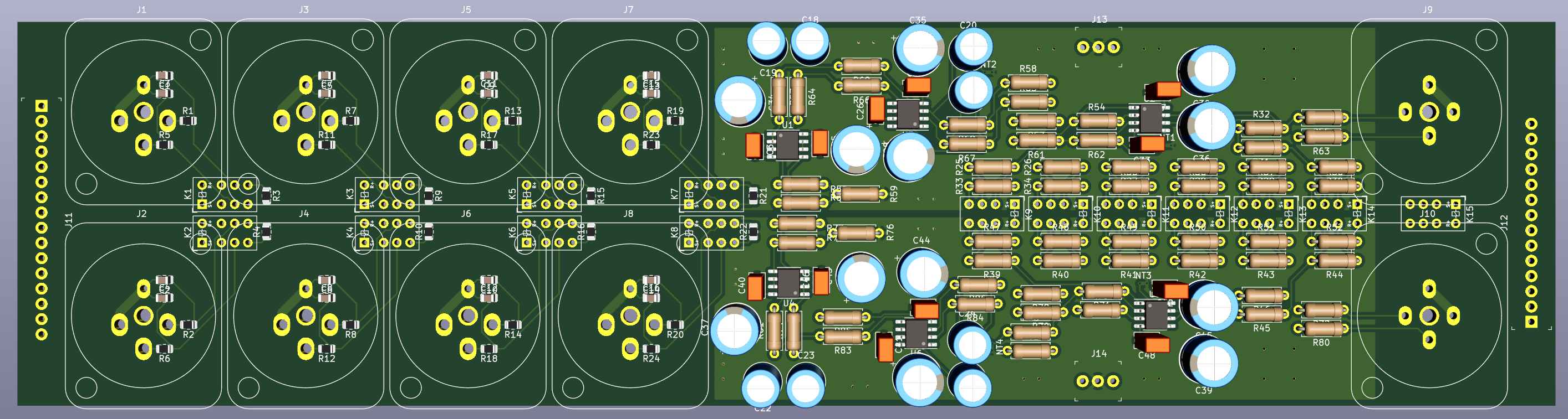
I'll be laying out my own PCB for this as I want to integrate the input switching, the volume control, and the linestage circuit all on the same PCB, which I'm hoping I can get narrow enough to mount vertically to the back panel with the XLR sockets soldered directly to the board. If I can pull that off, there will be no board-to-board connectors in the signal path at all. Contrast that with my current arrangement:
XLR to I/O selector board - one connector;
I/O selector to volume control - one connector;
volume control to linestage input - two connectors;
linestage output back to I/O selector - two connectors;
I/O selector to output XLR - one connector.
7 connectors total!

