The psychosis continues-- I just started a new speaker project.
This will be a hybrid electrostat using an electrically-segmented, vertical wire stators and it will have (2) switch-selectable dispersion modes-- a non-segmented/narrow dispersion mode for solo listening and a segmented /wide dispersion mode for entertaining guests. This could be the holy grail or I could fall on my face.
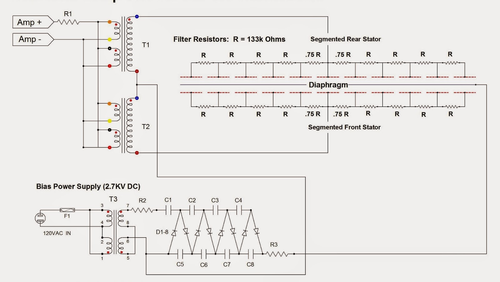
Each wire stator is an array of (132) .035" diameter copper coated welding rods. The welding rod conductors are physically segmented into (11) discrete groups of (12) wires and electrically segmented into (6) discrete groups; consisting of a center group and (5) paired groups on either side.
In narrow dispersion mode, all wire groups are directly coupled to the amps/transformers-- driving the diaphragm uniformly across its entire surface and the panel radiates a planar wave front, giving a tightly focused sweet spot for best imaging and slam.
In wide mode, dispersion is achieved the same way Peter Walker did it in the Quad ESL 63-- using electrically segmented conductors receiving sequentially delayed signals via a resistor/capacitor delay network.
But where the Quad 63 used concentric rings of conductors in a delay line, driving the diaphragm from the center outward as a point source radiating a spherical wave front, my panels use vertical wire groups driving the diaphragm from the centerline outward as a line source radiating a cylindrical wave front.
The wire segmentation and delay networks were derived using the Segmented ESL Calculator spread sheet developed by my friend Steve (a.k.a. "Bolserst") on the DIY Audio Forum. The capacitance of the wire groups themselves serve as the capacitors in the network so only resistors are required to build it.
The stators are very tedious to build: One stator completed--- three more to go:
New ESL speaker project
#1 New ESL speaker project
- Attachments
-
-
Last edited by Jazzman53 on Tue Mar 10, 2015 3:52 pm, edited 3 times in total.
-
shane

- Social outcast
- Posts: 3405
- Joined: Sun Sep 16, 2007 12:09 pm
- Location: Kept in a cool dry place.
#2
Wow!
How do you stop the whole assembly buzzing and rattling? I'd have thought that welding rod attached to a hard plastic frame would resonate like mad.
How do you stop the whole assembly buzzing and rattling? I'd have thought that welding rod attached to a hard plastic frame would resonate like mad.
The world looks so different after learning science. For example, trees are made of air, primarily. When they are burned, they go back to air, and in their flaming heat is released the flaming heat of the Sun which was bound in to convert air into tree.
#3
Well, I guess I will find out.shane wrote:Wow!
How do you stop the whole assembly buzzing and rattling? I'd have thought that welding rod attached to a hard plastic frame would resonate like mad.
The wires are glued every 1/2" where they cross each vane in the grid, using a resilient glue, which I hope will dampen the resonances.
I know at least one other builder on the DIY Audio Forum who uses the same method and he says they don't rattle or ring. That said, all ESL panels (perf-metal, plastic or whatever) will have two fundamental resonances. If you were to place your ear close to a panel (not playing) and tap on it, you would hear the diaphragm's drum-head resonance and also the resonance of the supporting structure.
BTW, I'm not building whole new speakers.... just replacing the perf-metal panels in my existing hybrid ESL's with these. My current ESL's have wonderful slam and imaging but their sweet spot is so tightly focused (narrow dispersion), they aren't much good for entertaining guests.
With these new panels, I should be able to quickly re-configure them for either narrow or wide dispersion.
My current speakers are shown here: http://jazzman-esl-page.blogspot.com/
-
izzy wizzy

- Old Hand
- Posts: 1496
- Joined: Fri Nov 02, 2007 7:02 pm
- Location: Auckland NZ
- Contact:
#4
The construction method is similar to how Acoustat made their panels except their stators used insulated wire. I owned some for 20+ years and they never buzzed or rattled. Still got the panels and interface boxes but now in storage.
I tried all kinds of frames. The sound or impact of the frame is significant but rigidity rather than mass is the thing to go for IMHO.
The other thing that makes a big difference is the bias supply.
Good luck. Great project.
cheers,
Stephen
I tried all kinds of frames. The sound or impact of the frame is significant but rigidity rather than mass is the thing to go for IMHO.
The other thing that makes a big difference is the bias supply.
Good luck. Great project.
cheers,
Stephen

#5 is there a link between dispersion and sweet spot?
I am not sure that there is a link between the two even if the audiophile press keeps repeating it because people believe it blindly.
I think that the problem is that the large surface area screws the sound up by phase error (which can be primitively displayed as less dispersion - but there is MUCH more going on).
Our listening works primarily with phase and not frequency response. The ability to locate sound sources uses this effect.
I think that the amount of interference generated increases with frequency. If the panel is lets say 50cm wide and we are only testing 1000Hz, we have wideband interference between the sound "sources" from 50 to 0cm apart. Some phase issues cause cancellation, some cause peaks. Conventional frequency response measurement just averages these things based on pressure vs frequency. Some pretty advanced modelling would be required to properly display this artifact.
So, I think that lowering acoustic interference would greatly increase the quality of the playback if you don't lose too much efficiency in the upper octaves.
It is the same effect in reverse that increases the sense of slam: acoustic cancellation lowers the amount of room gain (<300Hz) and gives you the impression of more slam. Power response however is a big deal in live music.
Quad did some VERY interesting things with delay to solve the issue.
I think that your dispersion mode could end up being the "truth" mode and the full mode would be the interference mode with the well defined "issues". You just need enough efficiency to keep conventional distortion down.
The first panel looks great. Can't wait to see the rest.
Whenever I feel blue, I start breathing again.
#6
Update 2/13:
Hi all,
I've been down with bronchitis for a while but the project is now back on.
All four stators are completed, the diaphragms are tensioned and bonded to the front stators, and minutes ago I sprayed the conductive coating on the diaphragms. I will let the coatings dry overnight, then assemble the panels in the morning.
Jazz
I've attempted to an a URL link to my build photos but I can't make it work here.
#7
Update 3/2/15:
I've finished the project except for wiring in the rotary switches that will be used to switch between wide and narrow dispersion modes. At this time the stator conductor groups are wired for wide dispersion mode only.
I will update again when I've had a chance to evaluate both dispersion modes. As of now, the speakers are fined tuned and sounding wonderful.
These new segmented panels do not have quite the magical imaging that my old narrow dispersion, non-segmented perf-metal panels had, but neither do that have the restrictive "head-in-a-vise" sweet spot.
Hopefully when the switches are wired I will have a choice of narrow or wide dispersion by simply turning a switch.
Here is a link to the write-up and build photos on my web page:
http://jazzman-esl-page.blogspot.com/20 ... -with.html
-
IslandPink

- Amstrad Tower of Power
- Posts: 10041
- Joined: Tue May 29, 2007 7:01 pm
- Location: Denbigh, N.Wales
#8
Good effort  That looks like a very non-trivial thing to do. Some skill honed over a number of years there, I guess ?
Is the tensioning of the diaphragm ( evenly ) quite a difficult task ?
What does the resistor network achieve ( to someone ignorant of the way these ESL's work ! ) .
Is the tensioning of the diaphragm ( evenly ) quite a difficult task ?
What does the resistor network achieve ( to someone ignorant of the way these ESL's work ! ) .
"Once you find out ... the Circumstances ; then you can go out"
#9
IslandPink wrote:Good effort
Is the tensioning of the diaphragm ( evenly ) quite a difficult task ?
What does the resistor network achieve ( to someone ignorant of the way these ESL's work ! ) .
The resistor network is a sequential time-delay-line. When switched in (wide mode), its resistances couple with the capacitances between wire groups (in opposing stators) to sequentially time delay the impulses fed to the center and adjacent wire groups. The diaphragm is then driven from its centerline outward and emits a cylindrical wave front.
With the delay line switched out (narrow mode) all wire groups are fed simultaneous impulses. The diaphragm is then driven across its entire area simultaneously and emits a planar wave front.
I've gotten pretty proficient at building perf-metal-stator ESL's but but these were my first electrically segmented wire-stator ESL's. It was a lot of tedious work and a definite learning experience. For this build I opted to use horizontal spacers to support the diaphragm, since the wires were arranged vertically.
The rule of thumb for diaphragm support spacers is that the span between them must not exceed 100 x d/s (diaphragm-to-stator gap); which was 0.062". Thus, for .062 d/s, the max span between supports would be about 6" and mine were close to that.
And since I had pushed the limit on the span between supports, I felt the need to tension the diaphragm quite high (1.75% elongation) to prevent accoustic coupling from the woofer from driving the diaphragms into the stators on bass notes. The high diaphragm tension put the diaphragms fundamental resonance (the drum-head resonance) at around 115 Hz, which is higher than I anticipated it would be a it caused problems.
Unlike conventional drivers, a 6-micron ESL diaphragm has such so low moving mass and inertia that it's effectively dampened by the air it's immersed in to extent that it simply cannot ring or overshoot the waveform. The only resonance it has is the fundamental; which can be nasty loud. My rule of thumb for dealing with the resonance in a hybrid ESL is to set the crossover frequency at least one octave above the diaphragm resonance using a 48db/octave filter slope, or at least 2 octaves above it if using a 24db/octave slope.
Tensioning the diaphragm evenly in both directions is quite easy if using a pneumatic bike tube jig. For this build, I opted for a mechanical jig because I wanted most of the tension to be in the vertical dimension.
Lessons learned: next time would use less span between support spacers and limit the tension to 1.5% elongation. Also, would use insulated wires to eliminate having to paint them.
The panels are sounding really good now... in the next week or so I will wire in the switches to allow selecting between narrow and wide dispersion.
Hope that helps...
Charlie
Last edited by Jazzman53 on Wed Mar 11, 2015 12:31 pm, edited 2 times in total.
-
jack

- Thermionic Monk Status
- Posts: 5502
- Joined: Wed Dec 29, 2010 8:58 pm
- Location: ɐılɐɹʇsnɐ oʇ ƃuıʌoɯ ƃuıɹǝpısuoɔ
- Contact:
#10
Very impressive - I'll watch this one with interest.
My recently-acquired ESL-63s are in a tatty state ATM - haven't even powered them up yet (they were a gift), but considering their life to date, I'm expecting to have to do a rebuild of some sort...
My recently-acquired ESL-63s are in a tatty state ATM - haven't even powered them up yet (they were a gift), but considering their life to date, I'm expecting to have to do a rebuild of some sort...
Vivitur ingenio, caetera mortis erunt
-
IslandPink
- Amstrad Tower of Power
- Posts: 10041
- Joined: Tue May 29, 2007 7:01 pm
- Location: Denbigh, N.Wales
#11
Thanks Charlie, that's really interesting !
"Once you find out ... the Circumstances ; then you can go out"
#12
A sketch to clarify the filter network:

#13
Having built ESL speakers in the past I find this build very interesting indeed and it would seem you really do know your stuff when it comes to ESL's.
I used to build the Rob Mackinlay ER Audio speakers and Rob used to have seperate Bass, midrange and treble panels using perforated metal stators and he developed a novel and very easy method of getting an even tention on the Mylar film diaphragms using a flat panel door and a small set of pull scales used by anglers. As you have done each of the panels was fed by a grid of resistors through dedicated TX to restrict the frequency to that panel and the panels were set in slight circle to help radiate sound in an attempt to get over the very narrow sweat spot.
Great work.
PS. If you could reduce the size of your above attached circuit diagram image it would get over the having to scroll right to read new postings and so get back to a single page format. makes following the thread so much easier.
#14
Thanks Toppsy,
I’ve read great reviews on the quality and sound of the ER Audio kits and their prices are certainly reasonable.
I’ve built perf-metal panels and their power supplies from scratch in a 3-day weekend but segmented wire panels are a whole lot more work. Fortunately I have smart friends on the DIY Audio Forum who helped out on this build.
There is a detailed guide to building perf-metal ESL’s and also a more detailed write up of this project on my ESL web page here:
http://jazzman-esl-page.blogspot.com/[u ... e [/img]
#15
Thanks Toppsy,
I’ve read great reviews on the quality and sound of the ER Audio kits and their prices are certainly reasonable.
I’ve built perf-metal panels and their power supplies from scratch in a 3-day weekend but segmented wire panels are a whole lot more work.
Fortunately I have smart friends on the DIY Audio Forum who helped out on this build.
There is a detailed guide to building perf-metal ESL’s and also a more detailed write up of this project on my ESL web page here:
http://jazzman-esl-page.blogspot.com/
I was inspired to do this build by Ken Seibert’s ESL Page here:
http://kenseibert.com/www/kenseibert/esl/
Another builder, Steve Bolserst, developed this Excel Segmented ESL Calculator that I used:
http://www.diyaudio.com/forums/attachme ... diy_v2.zip
Enjoy!
Charlie