Input transformers

We all start somewhere
User avatar
pre65
Amstrad Tower of Power
Posts: 21399
Joined: Wed Aug 22, 2007 11:13 pm
Location: North Essex/Suffolk border.

#1 Input transformers

Post by pre65 »

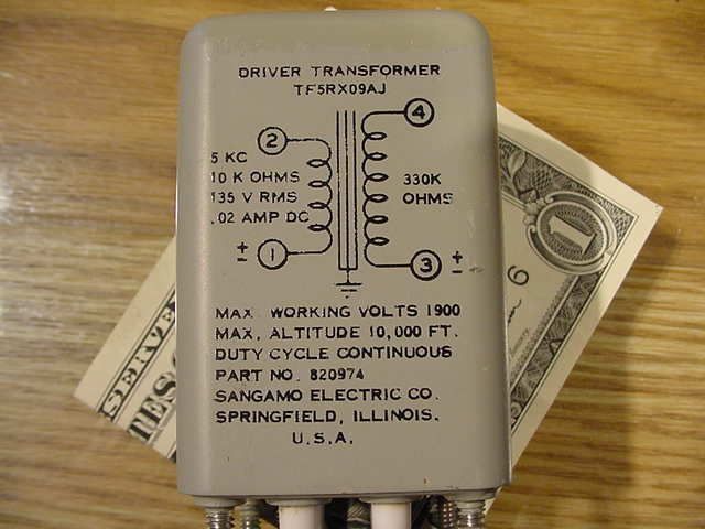
I was looking at some input transformers that have a primary of 10K and a secondary of 330K

So the impedance ratio is 10,000/330,000 = 0.03

And the voltage (turns) ratio is 0.17

So, the voltage goes down and the current goes up ?

Confused from Essex (very nearly Suffolk). :wink:
The only thing necessary for the triumph of evil is for good men to do nothing.

Edmund Burke

G-Popz THE easy listening connoisseur. (Philip)
User avatar
Mike H
Amstrad Tower of Power
Posts: 20189
Joined: Sat Oct 04, 2008 5:38 pm
Location: The Fens
Contact:

#2

Post by Mike H »

It's step up (10k > 330k)

= Imp ratio 1:33

= Turns/V ratio as square root of 33, = 1:5.744

Voltage is increased, current is decreased, power stays the same (minus losses)

Don't forget the losses include (or mainly consist of?) winding resistances which will be in series with the input and output impedances, these will add Voltage drops and hence may result in lower Voltage output than you expect. I say 'may', in case the designer has compensated for it.

HTH (?)
 
"No matter how fast light travels it finds that the darkness has always got there first, and is waiting for it."
Steptoe
User
Posts: 76
Joined: Thu Mar 13, 2014 8:26 am

#3 input transformers

Post by Steptoe »

It is now the turn of confused from WA. Is it possible to work out the turns ratio from the impedance or does that also depend on the thickness of the wire? for example, if the 2* was made with very thin wire could"nt that result in an apparent increase in the number of turns? Your advice would be most welcome. Steptoe.
User avatar
Mike H
Amstrad Tower of Power
Posts: 20189
Joined: Sat Oct 04, 2008 5:38 pm
Location: The Fens
Contact:

#4

Post by Mike H »

No, apparent decrease in number of turns, there will be a Voltage drop across the wire resistance so will be like FEWER turns for less Voltage.

Increasing the load on the secondary will make it worse.

It's possible to increase the number of turns to compensate for the resistance drop, BUT will be correct only at one load impedance value.

But then you will lose power, because e.g. increasing secondary turns lowers the current, so OK Voltage will be correct, but output power is lower than the input.

HTH?
 
"No matter how fast light travels it finds that the darkness has always got there first, and is waiting for it."
User avatar
Nick
Site Admin
Posts: 15751
Joined: Sun May 06, 2007 10:20 am
Location: West Yorkshire

#5 Re: input transformers

Post by Nick »

Steptoe wrote:It is now the turn of confused from WA. Is it possible to work out the turns ratio from the impedance or does that also depend on the thickness of the wire? for example, if the 2* was made with very thin wire could"nt that result in an apparent increase in the number of turns? Your advice would be most welcome. Steptoe.
No, I think you are confusing impedance with resistance. The impedance ratio of a transformer is a bit of a fiction, all that matters is the ratio of the number of turns. That ratio controls the step up/down figure. Using impedances is a convenient way of describing the ratio.

Describing a output transformer as 5k into 8R is simpler to think about than a turns ratio of 25:1 because we know what load the loudspeaker presents, and what load we waht the output device (valve) to work into.

If you have a 10k:330k transformer, the primary will only look like 10k, if the secondary has a 330k load applied. Apply a 500k load, and the primary will look like a 15k load.

The only time those impedance numbers MAY have some meaning, is if the capacitance of the windings means that the transformer MAY give its best frequency response when driving into and from those impedances.
Whenever an honest man discovers that he's mistaken, he will either cease to be mistaken or he will cease to be honest.
User avatar
pre65
Amstrad Tower of Power
Posts: 21399
Joined: Wed Aug 22, 2007 11:13 pm
Location: North Essex/Suffolk border.

#6

Post by pre65 »

So, would the 10K / 330K step up transformer be any use as an input transformer on a single stage valve amp ?

It's rated on the primary as 0.02A.
The only thing necessary for the triumph of evil is for good men to do nothing.

Edmund Burke

G-Popz THE easy listening connoisseur. (Philip)
User avatar
Nick
Site Admin
Posts: 15751
Joined: Sun May 06, 2007 10:20 am
Location: West Yorkshire

#7

Post by Nick »

pre65 wrote:So, would the 10K / 330K step up transformer be any use as an input transformer on a single stage valve amp ?

It's rated on the primary as 0.02A.
Hard to say, it could. I dont understand what the 20ma means in this context. is it gapped? It would be better not playing 20 questions.
Whenever an honest man discovers that he's mistaken, he will either cease to be mistaken or he will cease to be honest.
User avatar
Paul Barker
Social Sevices have been notified
Posts: 8985
Joined: Mon May 21, 2007 9:42 pm

#8 Re: input transformers

Post by Paul Barker »

Steptoe wrote:It is now the turn of confused from WA. Is it possible to work out the turns ratio from the impedance or does that also depend on the thickness of the wire? for example, if the 2* was made with very thin wire could"nt that result in an apparent increase in the number of turns? Your advice would be most welcome. Steptoe.
You are confusing resistance with impedance.

The thickness of the wire affects the resistance. The turns ratio affects the impedance.
"Two things are infinite, the universe and human stupidity, and I am not yet completely sure about the universe." – Albert Einstein
Steptoe
User
Posts: 76
Joined: Thu Mar 13, 2014 8:26 am

#9 input transformers

Post by Steptoe »

Dear all, thank you for your comments but sadly you have grossly underestimated my degree of confusion. I haven't previously come across this way of describing a transformer but I thought that its impedance was a combination of inductance and DC resistance according to a complicated formula involving square roots of sums of squares, so a much higher DC resistance in one winding would give a false indication of the turns ratio.

I confess to being on very shaky ground here because I obtained my information from a book written by one Prof. Langford Smith, who lost me once he started talking about the square root of -1, which can"t possibly exist as a single entity.

To paraphrase Haldane, I am probably at a stage where the concepts are not only stranger than I think, but are stranger than I can think,
so it is probably a waste of time trying to explain them to me, but thank you for trying. With best wishes, Steptoe.
User avatar
Nick
Site Admin
Posts: 15751
Joined: Sun May 06, 2007 10:20 am
Location: West Yorkshire

#10

Post by Nick »

I am sorry for the pun, but the square root of -1 is very real. It exists in just the same was as the number -1 or e exists.

Not you may question the word "exist" in the above, but that's a different matter.

So much becomes possible to describe if you use the complex number plain. Much of electronic theory would not be possible without of it.
Whenever an honest man discovers that he's mistaken, he will either cease to be mistaken or he will cease to be honest.
User avatar
pre65
Amstrad Tower of Power
Posts: 21399
Joined: Wed Aug 22, 2007 11:13 pm
Location: North Essex/Suffolk border.

#11

Post by pre65 »

Nick wrote:
pre65 wrote:So, would the 10K / 330K step up transformer be any use as an input transformer on a single stage valve amp ?

It's rated on the primary as 0.02A.
Hard to say, it could. I dont understand what the 20ma means in this context. is it gapped? It would be better not playing 20 questions.
This is all I have on the item. They are for sale in USA in a lot of 10. If they are any good perhaps others might want to try them ? I don't need 10 for my own use.

EDIT. Ohm-out tested : Pri (1-2) DCR= 40 Ohms, Sec (3-4) DCR=730 Ohms. That is all ( no more information available)

Image
The only thing necessary for the triumph of evil is for good men to do nothing.

Edmund Burke

G-Popz THE easy listening connoisseur. (Philip)
User avatar
Nick
Site Admin
Posts: 15751
Joined: Sun May 06, 2007 10:20 am
Location: West Yorkshire

#12

Post by Nick »

Ok, so at 20ma, they are gapped, and I expect they are designed be driven by something like a 6sn7.
Whenever an honest man discovers that he's mistaken, he will either cease to be mistaken or he will cease to be honest.
User avatar
pre65
Amstrad Tower of Power
Posts: 21399
Joined: Wed Aug 22, 2007 11:13 pm
Location: North Essex/Suffolk border.

#13

Post by pre65 »

Nick wrote:Ok, so at 20ma, they are gapped, and I expect they are designed be driven by something like a 6sn7.
OK, thanks for that.

In your opinion, what would be a good way to use a transformer like these ?
The only thing necessary for the triumph of evil is for good men to do nothing.

Edmund Burke

G-Popz THE easy listening connoisseur. (Philip)
User avatar
Paul Barker
Social Sevices have been notified
Posts: 8985
Joined: Mon May 21, 2007 9:42 pm

#14

Post by Paul Barker »

I would say whoopee count me in, but I can't decide what 5kc stands for. If it is 5 kHz (derived from the old name of cycles for frequency) then it is as much use to us as a one legged man in a bum kicking contest.

the 5KC is the deciding factor.

It wouldn't be the first time that I bought high frequency transformers by mistake.

Just 'cause it says "driver transformer" doesn't mean it has to drive full range.
"Two things are infinite, the universe and human stupidity, and I am not yet completely sure about the universe." – Albert Einstein
User avatar
Paul Barker
Social Sevices have been notified
Posts: 8985
Joined: Mon May 21, 2007 9:42 pm

#15 Re: input transformers

Post by Paul Barker »

Steptoe wrote:Dear all, thank you for your comments but sadly you have grossly underestimated my degree of confusion. I haven't previously come across this way of describing a transformer but I thought that its impedance was a combination of inductance and DC resistance according to a complicated formula involving square roots of sums of squares, so a much higher DC resistance in one winding would give a false indication of the turns ratio.

I confess to being on very shaky ground here because I obtained my information from a book written by one Prof. Langford Smith, who lost me once he started talking about the square root of -1, which can"t possibly exist as a single entity.

To paraphrase Haldane, I am probably at a stage where the concepts are not only stranger than I think, but are stranger than I can think,
so it is probably a waste of time trying to explain them to me, but thank you for trying. With best wishes, Steptoe.
you're reading too much into it, the dc resistance creates some minor losses, but it is largely irrelevant to impedance calculation. It represents a final power loss. Whilst it is true that a quality transformer would factor this element in. For establishing what Phil's transformers are it's not in the ball park.
"Two things are infinite, the universe and human stupidity, and I am not yet completely sure about the universe." – Albert Einstein
Post Reply