Hi Simon
It may interest you to know that I went back and read and reread your posts multiple times, and I thought they were all making sense finally. But I didn't know about roll off. I've got to drive to Dublin tomorrow for an interview for my entry visa for Ireland and won't be back till tomorrow evening. So no more posts from me till then.
I appreciate the argument about keepng R12a and b the same as R17. But Broskie only supplied up to 200 R 1 W resistors for R17 but the range for R12a and b was much higher and ended at 10 K. So I cant match R17 and R12 from the kits he supplied and I think I will let it go unless you come up with other suggestions.
I've soldered on all the diodes and tested that they conduct in one direction only with about -.4 to -.6 V. I've soldered on all the resistors except for the ones we were discussing so much, and have tested that the resistance is there. For the resistors we've discussed so much, I've soldered pins on for soldering on the bottom of the board using 10% silver solder so they won't melt as readily. And I've soldered on R12 and R17 for your configuration of 300 V. This is one board I am not showing people pictures of at this point! Tacking these resistors onto pins to use Nick's phrase is a bummer, took me forever, looks lousy. But the desired resistance of 1300 R across both R12s is there for both channels and 200 R for R17. I'm going to stop for now and then solder on the R3, R4, R6 and R7 when I get back.
To make up for this lousy soldering and because the exact resistors I wanted weren't in Broskie\s kit, I've ordered 200R 270R and 100 R in various high quality names from HiFi Collective in 1 W and 2 W sizes, and we can use them with comparing voltages.
I won't hear anything for a month or more because the box for the Variac win't be ready till then and I still don't have a case designed or ordered. I'm also reluctant to connect the TXs until I have some expert DIYers looking over my shoulders.
all my best
Mark
Help on assembling an Aikido 5687 kit
#62
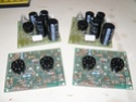
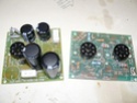
You're doing better than I did! I've dug out the part built DiyAudio boards I have and I'll put a couple of pics on tomorrow. I also have a link to a DiyAudio thread regarding Aikido calculations if you're interested. I don't want to put it up if it's going to cloud things. With a bit of luck if I keep reading this thread I might get my Aikido finished 
#63
Hi, do post the pictures. It has to look better than what I jusy did with trying to tack to the pins. And usinf jumpers from trimmed off resistor leads doesn't look pretty either in my hands.Chopsaw wrote:You're doing better than I did! I've dug out the part built DiyAudio boards I have and I'll put a couple of pics on tomorrow. I also have a link to a DiyAudio thread regarding Aikido calculations if you're interested. I don't want to put it up if it's going to cloud things. With a bit of luck if I keep reading this thread I might get my Aikido finished
And do post the link.
Mark
#64
Ok, here are my DiyAudio boards,
And this is the link http://www.diyaudio.com/forums/tubes-va ... tions.html
And this is the link http://www.diyaudio.com/forums/tubes-va ... tions.html
#65 Re: Could you please check these values?
Sorry, C5 is 270 uF 220V abd C7 and C8 are 220 uF 220V. It is not clear to me how to calculate the frequency since C7 and C8 are paralleled across R17. Assuming that each sees the same R value of 200R, which makes little sense, their cutoff would be 2.2 lower than 8 Hz or about 4 Hz.simon wrote:Right Mark, been rather bogged down for a few days - you've probably already got this thing built
Now your Brucey bonus is your power supply. The figures for R17, R12a and R12b are perfectly valid, and numerically correct. But, the resistors and capacitors form filters that roll off the bass response. I don't know what values JRB supplies for C5, C7 and C8, but for the sake of this exercise let's assume they're all 100uF.
Their voltage ratings were each 220V. As noted above I'm not sure how to handle power calculations when C7 and C8 are parallled across R17.simon wrote: Don't forget to check the power rating of the resistors BTW, you can get a bit of a surprise if you don't. And for paralleled resistors of different values don't forget the current flowing through each will be different...
Incidentally what's the voltage rating of caps C5, C7 and C8? You need to make sure that they don't go over-voltage on power up before the valves have warmed up and start conducting.
I have now finished soldering all the resistors. As noted in a previous post, the soldering on pins is not fit to show in public but all the resistors are providing appropriate resistance.
I noticed that there is no R23 included in the package which is supposed to be connected to C3b, which is also missing. There is only a C3 (also labelled C3a), but looking at the wiring the circuit should function without C3b and R23 because C3b is in parallel to C3. I've assumed that I can skip this.
I've understood the circuit to mean that I need to jumper J3, which is mispelled as J13 at another position, and have done so.
Almost all resistors are 1/2 W except R12a and b which were 3 W, R13-R19 which was 1W.
I've now started on the caps. Please confirm that when a polarity is given for a cap, the longer lead is + and the white stripe repesents the opposite - polairty. And that the large electrolytic caps and small ceramic caps do not have polarity for soldering. At least there aren't any markings on the PCB or on the caps. I've tried to measure the microfarads on the caps with my multimeter but have failed, both with unsoldered and with soldered caps. Is there a trick to measuring whether they are intact after soldering? Soldering some of the metal canned caps is a major problem because they are acting as heat sinks and I'm having problems getting the solder to flow. Any and all tips welcome. Especially for how to solder the hear sink which should swall all of the heat according to my simple minded expectations.
I've stuck the big electrolytic plastic looking caps on the board with double side tape which bought from Broskie for $5. I now have the metal cans and ceramic caps and heat sink plus voltage regulator left.
Once we're done with this part, I would like to discuss the case.
best regards
Mark
#67
I'm already on the case. This thread you posted up spurred me into doing something about it. The electrolytics on the psu boards were bought last week and I finally fitted the cathode resistors which I already had. I cheated with the cathode resistors and put in values as per one of the diagrams in the link I posted. I'm still struggling to work it out but maybe some of us are just not gifted enough to grasp such things.
#68 Finished PCB
I said I wouldn't post any pictures because I a so ashamed of my soldering but the Pearl coolers look neat.
Back Side: http://campl.us/dbSa44ZTFBY
Side views: http://campl.us/ff2ke1H2Qxg
http://campl.us/ilFYkBJUiiq
Top View: http://campl.us/dCVqemBn4bA
Every last overlit detail: http://campl.us/jv99kkPLqgK
and in case you get hungry
http://campl.us/cFN7nNuQ4US
This was tough for me to solder. It took forever for some of the caps and I had to play with temperature on the soldering iron and size of the bit. I'm learning but heavy handed would still be a compliment. However, all the resistors have approximately the right resistance, all the diodes only show a voltage drop in one direction, and all of the caps have contact with the soldered connection and the next position they are supposed to be in electrical contact with.
I made one mistake, forgetting to worry about the polarity of the C13 and C14 caps until I had soldered them, and luckily had placed them in the correct orientation for a full wave bridge rectifier. Unfortunately, it will be >3 weeks before the variac and preamp cases are finished and I'm not testing anything until both are ready.
All comments welcome, even loud sneers of derision. Except the food, which is a matter of taste.
Mark
-
simon
- Thermionic Monk Status
- Posts: 5643
- Joined: Thu May 24, 2007 11:22 am
- Location: People's Republic of South Yorkshire
#71
Things are very busy at the moment Mark, so I haven't been much help I'm afraid, sorry.
I've just had a quick catch up on the thread and there are a lot of questions which I'll try to answer in time, but the first thing is the voltage rating of C5, C7 and C8 - it's only 220V and you're planning on putting 350V across some of them which is bad. Very bad. Let me repeat that, you're planning on putting 350V across caps rated at 220V - you will kill the caps pretty quickly. If you're going to start it up on a variac then you'll be okay as long as you check the voltage on top of the first cap with a multimeter and stop before you get to 220V. B ut you need to change the caps for higher ratings if you're going to use this at higher voltages.
We like photos here, we like 'em a lot so thanks for posting . It also really helps sometimes cos now I can see that JRB has supplied you with a kit for headphones as you have the 30uF Dayton coupling caps. JRB uses these for coupling to 300 ohm headphones. You don't need anything like that size - if you do the maths you'll see, it's the same frequency calculation we did for R12 and R17. But remember that the R will be in parallel with the impedance of the following power amp. Generally something between 1uF and 4uF will be fine. But you won't break anything using the big Dayton.
I've just had a quick catch up on the thread and there are a lot of questions which I'll try to answer in time, but the first thing is the voltage rating of C5, C7 and C8 - it's only 220V and you're planning on putting 350V across some of them which is bad. Very bad. Let me repeat that, you're planning on putting 350V across caps rated at 220V - you will kill the caps pretty quickly. If you're going to start it up on a variac then you'll be okay as long as you check the voltage on top of the first cap with a multimeter and stop before you get to 220V. B ut you need to change the caps for higher ratings if you're going to use this at higher voltages.
We like photos here, we like 'em a lot so thanks for posting
-
simon
- Thermionic Monk Status
- Posts: 5643
- Joined: Thu May 24, 2007 11:22 am
- Location: People's Republic of South Yorkshire
#72
It sounds like they might have revised the trafo specs then. Definitely wise to make sure you're not overstressing it current-wise. The operating points aren't an exact science, the odd mA won't make much difference.machtman wrote:According to the description of the 369AX I downloaded from the internet, it should have 115 mA but the one that was shipped to me has the specifications 250VCT 100 mA DC for red-red/yel-red.
Don't get bogged down in this, it's one of JRB's lessons. All he's showing is that two different transformers are providing different voltages and current, but they're both using the same power. His manuals are more about learning than ABCs to how to build things, that's all.machtman wrote:I must also say that I am totally confused by an apparent discrepancy between your recommendations and the pictures by Broskie on p. 14. He shows a centre-tapped configuration at the top which leaves out diodes D3 and D4 and resistors R15 and R16. That produces 240Vct@120mA. The bottom non-centre-tapped transformer has all four diodes connected, which matches with your statement that one needs four transistors, but only indicates 120Vct at 180 mA.
There are two HT secondary windings, each one is good for 100mA, it just depends on how you wire up it up as to what you get out of it.machtman wrote:Based on this, it sounds as if the 100 mA specified for the TX might only be true when the centre tap is used and that there shouldn't be any problems
with excess current. But I thought we were using the non-centre-tapped version to provide 250V whereas the diagram shows half the voltage versus the CT version.
That big arrow pointing down is signal ground or earth. Generally it's 0V, i.e. connected to the earth pin of the incoming IEC, but it can be reasonably anything if suitably designed. The dashed line J13 is indicating the connection to chassis ground. This is very different to circuit ground as it earths all the metal bits that can be touched, hence the name chassis ground. You must make sure you have properly grounded your chassis or you'll have a death trap on your hands. Sometimes we "lift" the circuit ground from the chassis ground (via a suitable small resistor 10R to 100R) to eradicate hum loops.machtman wrote:Broskie is also confusing me with jumper J13, which always looks as if it is not connected to the chassis ground and I don't understand the meaning of the big arrow pointing down but not connected to anything.
-
simon
- Thermionic Monk Status
- Posts: 5643
- Joined: Thu May 24, 2007 11:22 am
- Location: People's Republic of South Yorkshire
#73 Re: Could you please check these values?
Sorry to labour the point, but it's a vital one to make - your caps are not rated high enough for the intended use, 450V rating should be enough I'd guess.machtman wrote:Sorry, C5 is 270 uF 220V abd C7 and C8 are 220 uF 220V.
Each one will form a filter - C7 with R17, R17 with C8, C8 with R12, R12 with C4+C5.machtman wrote:It is not clear to me how to calculate the frequency since C7 and C8 are paralleled across R17. Assuming that each sees the same R value of 200R, which makes little sense, their cutoff would be 2.2 lower than 8 Hz or about 4 Hz.
I can't see R23 in the manual. Are you using more than one coupling cap? I think I remember you saying you were going to, along with one of JRB's switches? If so I'd guess that R23 is the equivalent of R11? So if you use two coupling caps use two resistors, make sure the caps aren't in parallel.machtman wrote:I noticed that there is no R23 included in the package which is supposed to be connected to C3b, which is also missing. There is only a C3 (also labelled C3a), but looking at the wiring the circuit should function without C3b and R23 because C3b is in parallel to C3. I've assumed that I can skip this.
You definitely need a connection, but you might use a resistor to lift the circuit earth.machtman wrote:I've understood the circuit to mean that I need to jumper J3, which is mispelled as J13 at another position, and have done so.
Most electrolytics have polarity, and they're marked with a white stripe which should have a minus sign on it.machtman wrote:I've now started on the caps. Please confirm that when a polarity is given for a cap, the longer lead is + and the white stripe repesents the opposite - polairty.
Please check - most lytics have polarity. If you connect them the wrong way round they can make a real mess when they go bang. Really.machtman wrote:And that the large electrolytic caps and small ceramic caps do not have polarity for soldering. At least there aren't any markings on the PCB or on the caps.
No substitute for a high powered iron, preferably temperature controlled at the tip. If you're struggling try non-silver solder.machtman wrote:Soldering some of the metal canned caps is a major problem because they are acting as heat sinks and I'm having problems getting the solder to flow. Any and all tips welcome. Especially for how to solder the hear sink which should swall all of the heat according to my simple minded expectations.
#74
Hi Simon, this is really great of you to take this much time on this project. Could you possibly be more specific and provide a manufacturer and part number for 440 V replacements for C5, C7 and C8 which are of high to very high quality? I suspect I will end up using the 350 V in the end based on your experience and I might as well replace them here before I pack everything away for the move,simon wrote: but the first thing is the voltage rating of C5, C7 and C8 - it's only 220V and you're planning on putting 350V across some of them which is bad. Very bad.
Again, if you can provide me with part numbers and recommendations, that would be great. There may have been a choice of caps and I took what I thought were better because they were more expensive.simon wrote: I can see that JRB has supplied you with a kit for headphones as you have the 30uF Dayton coupling caps. JRB uses these for coupling to 300 ohm headphones. You don't need anything like that size
In this case using smaller caps would be great because the huge caps are pushing the vertical caps next them out of vertical. Similarly, if there were smaller high quality caps for C4, I would want to replace them because they are extremely close to the Pearl coolers in the photos, and I wouldn't mind replacing them with smaller caps that give me more space.
I note that all the vertical metal caps had white stripes and I put those in the -ve PCB hole and the longer leads at the other end in the +ve PCB hole. However, the Daytons, the bid red C4s and the quadratic C6's did not have any polarity markings and there was no polarity shown on the board for them.
As to your recommendations on caps, this board has already cost so much for tools, input jacks, rotaries, TXs and now the case that I'm having built, that I'm not too concerned about the price of new caps, and simply want to be sure that the sound will not be compromised in any way due to trying to save money on caps. I also don't want to have to desolder more often than once more to try even better and more expensive caps.
Thanks for all your help.
Mark
#75
The manual doesn't mention R23 and he didn't supply one. Similarly he didn't supply C3b. But there are holes for two R23 abd two C3b's on the board, which is why I was wondering whether they were needed and forgotten in the kit. For ecample, one resistor was inadvertebtly only supplied once where two were needed and I filled both of them with a matched pair from the resistor kit I bought on your recommendations.simon wrote: I can't see R23 in the manual. Are you using more than one coupling cap? I think I remember you saying you were going to, along with one of JRB's switches? If so I'd guess that R23 is the equivalent of R11? So if you use two coupling caps use two resistors, make sure the caps aren't in parallel.
"
I am not using his switch which he is not selling at the moment and I didn't want to put in an extra pair of cap plus resistor, but just wanted to make a minimal system to see how it sounds and what it involves.
Thanks again
Mark
Mark