Beginners regulated PSU.

We all start somewhere
User avatar
pre65
Amstrad Tower of Power
Posts: 21400
Joined: Wed Aug 22, 2007 11:13 pm
Location: North Essex/Suffolk border.

#1 Beginners regulated PSU.

Post by pre65 »

I've been reading Steves regulated PSU tutorial, and need to ask a question.

I have some octal gas regulator tubes (0D3) that are 150v.

So if I use an EL34 (which I have got) and the HT is 340v, the valve will see 340-150v = 190v across it. So going by the chart at 190v and 45 - 50ma (not quite sure yet) the bias would be approx -12v.

Have I got that right so far ?

Bugger, the 0D3 has a max rating of 40ma. :( :(

OK, if using a single PSU could one run two regulators off it ? And if so would the PSU have to provide twice the total current, or four times ?
The only thing necessary for the triumph of evil is for good men to do nothing.

Edmund Burke

G-Popz THE easy listening connoisseur. (Philip)
User avatar
Paul Barker
Social Sevices have been notified
Posts: 8991
Joined: Mon May 21, 2007 9:42 pm

#2

Post by Paul Barker »

Too vague a description Phil. draw what is in your head because I can't see it from your words. then I can help you.
"Two things are infinite, the universe and human stupidity, and I am not yet completely sure about the universe." – Albert Einstein
User avatar
Paul Barker
Social Sevices have been notified
Posts: 8991
Joined: Mon May 21, 2007 9:42 pm

#3

Post by Paul Barker »

If you are limited in your vr tube availability try the schematic no 9 on this page.
Image

In pass regs all you use the vr tube for is a known voltage that won't vary considerably around which to set a valves characteristics so that those characteristics will allways try to rain other variables back from change.

You can just as easily use a battery as a voltage reference. In the schematic no. 9 the VR tube could be replaced by a battery. You just need either on the cathode or the grid of the voltage sampling element a fixed reference.

The characteristics of in this case (fig 9) a pair of valves any other factors which change will inspire the vlave to counter that change aslong as the one element (grid or cathode) never changes.

Figure 6 looks good but the battery would be high voltage. Impractical for you.
"Two things are infinite, the universe and human stupidity, and I am not yet completely sure about the universe." – Albert Einstein
User avatar
Paul Barker
Social Sevices have been notified
Posts: 8991
Joined: Mon May 21, 2007 9:42 pm

#4

Post by Paul Barker »

The whole of that article is found here.
"Two things are infinite, the universe and human stupidity, and I am not yet completely sure about the universe." – Albert Einstein
User avatar
pre65
Amstrad Tower of Power
Posts: 21400
Joined: Wed Aug 22, 2007 11:13 pm
Location: North Essex/Suffolk border.

#5

Post by pre65 »

Paul Barker wrote:Too vague a description Phil. draw what is in your head because I can't see it from your words. then I can help you.
Here is my diagram. Would not a regulated supply for each channel be better ?

Image
The only thing necessary for the triumph of evil is for good men to do nothing.

Edmund Burke

G-Popz THE easy listening connoisseur. (Philip)
User avatar
Nick
Site Admin
Posts: 15752
Joined: Sun May 06, 2007 10:20 am
Location: West Yorkshire

#6

Post by Nick »

Paralleling shunt regs make no sense.
Whenever an honest man discovers that he's mistaken, he will either cease to be mistaken or he will cease to be honest.
User avatar
pre65
Amstrad Tower of Power
Posts: 21400
Joined: Wed Aug 22, 2007 11:13 pm
Location: North Essex/Suffolk border.

#7

Post by pre65 »

Nick wrote:Paralleling shunt regs make no sense.
Why ? That was one shunt per channel.

What about in a dual mono PSU ?
The only thing necessary for the triumph of evil is for good men to do nothing.

Edmund Burke

G-Popz THE easy listening connoisseur. (Philip)
User avatar
Cressy Snr
Amstrad Tower of Power
Posts: 10582
Joined: Wed May 30, 2007 12:25 am
Location: South Yorks.

#8

Post by Cressy Snr »

pre65 wrote:
Nick wrote:Paralleling shunt regs make no sense.
Why ? That was one shunt per channel.

What about in a dual mono PSU ?
Sorry phil but Nick is dead right.
That power supply and the two branches with regs means that you are parallelling up the regs.
It won't work.

Regulate then branch off.
Also a series reg is easier to implement for the beginner. Although it appears more complex in that it uses more parts there is far less danger of bangs and meltdowns with a series reg.
Paul did make that point about these sorts of problems s for the beginner in the original thread I did.
Sgt. Baker started talkin’ with a Bullhorn in his hand.
User avatar
pre65
Amstrad Tower of Power
Posts: 21400
Joined: Wed Aug 22, 2007 11:13 pm
Location: North Essex/Suffolk border.

#9

Post by pre65 »

That's fair enough Steve, but your tutorial is all I had to go on.

My mains transformer has two secondary's so I could go dual mono.

It's a pity, because I actually understood what you had written about shunt regulators, you made it so clear and concise. :)
The only thing necessary for the triumph of evil is for good men to do nothing.

Edmund Burke

G-Popz THE easy listening connoisseur. (Philip)
User avatar
Nick
Site Admin
Posts: 15752
Joined: Sun May 06, 2007 10:20 am
Location: West Yorkshire

#10

Post by Nick »

pre65 wrote:
Nick wrote:Paralleling shunt regs make no sense.
Why ? That was one shunt per channel.

What about in a dual mono PSU ?
You are thinking left to right, as I said in a long whitter, the electrons don't know what you intend. Topologically (same whitter) every point on a wire is connected to the same place.
Whenever an honest man discovers that he's mistaken, he will either cease to be mistaken or he will cease to be honest.
User avatar
pre65
Amstrad Tower of Power
Posts: 21400
Joined: Wed Aug 22, 2007 11:13 pm
Location: North Essex/Suffolk border.

#11

Post by pre65 »

OK, it's cos in some ways I'm a bit thick. :wink:

I'll do a detailed drawing of how I understand Steves tutorial for using a shunt reg for one channel in a dual mono power supply.

This will be an exercise for me, to show I have understood what teacher kindly showed us. I understand the caveats added after the notes. If I pass the test it will boost my confidence and encourage me to take more steps in the theoretical learning path.

If I did go ahead with this project the first iteration would likely use an anode CCS (for several reasons) so I'm in no rush to go regulated. :wink:
The only thing necessary for the triumph of evil is for good men to do nothing.

Edmund Burke

G-Popz THE easy listening connoisseur. (Philip)
User avatar
Paul Barker
Social Sevices have been notified
Posts: 8991
Joined: Mon May 21, 2007 9:42 pm

#12

Post by Paul Barker »

Image

The 10k resistor is to protect the VR from the 6.8uF cap. The pot should be nominally 470k 500k.

Depends which VR you use as to what supply transformer you pick off the 1/2 wave rectified voltage reference. If you have two 150's you can negatively 1/2 wave rectify the main Ht . The current adjusting resistor is what absorbes the excess. Yes you can use a CCS in it's place. Then you could use a single 150v vr.

Or you can voltage multiply a spare filament voltage winding.

Use your imagination.

Now you are limited in shunt current by the EL34: 23 mA at 8 watts. So you need to find a more powerful valve.

With the 813 triode connected at your voltage if you limit yourself to -10v on the grid no closer to A2 operation than that it will shunt 120mA more negative grid voltage for more conservative shunt currents.

6C33C sky is your limit at 340v max is 176 mA. Which takes about 135v negative bias. With a 150v negative supply you aren't going to get it below 60mA you would need another vr tube to bring it down.

But you get the idea?

You shunt the same current at the very least that your signal section draws quiescent. Yes you can make one per channel. Is your transformer up to double the current? Also don't forget the dc resistances (transformer DCR, rectifier tubes, choke dcr) now drop double the voltage. Have you still got enough voltage available?

It will be big and heavy.
"Two things are infinite, the universe and human stupidity, and I am not yet completely sure about the universe." – Albert Einstein
User avatar
pre65
Amstrad Tower of Power
Posts: 21400
Joined: Wed Aug 22, 2007 11:13 pm
Location: North Essex/Suffolk border.

#13

Post by pre65 »

Thanks Paul, that's an interesting post. I will try and understand what it all means. :wink:

However, I'm still interested in the way Steve explained things. Now, I understand my original scheme is not a goer, but I'd still like to do something along those lines.

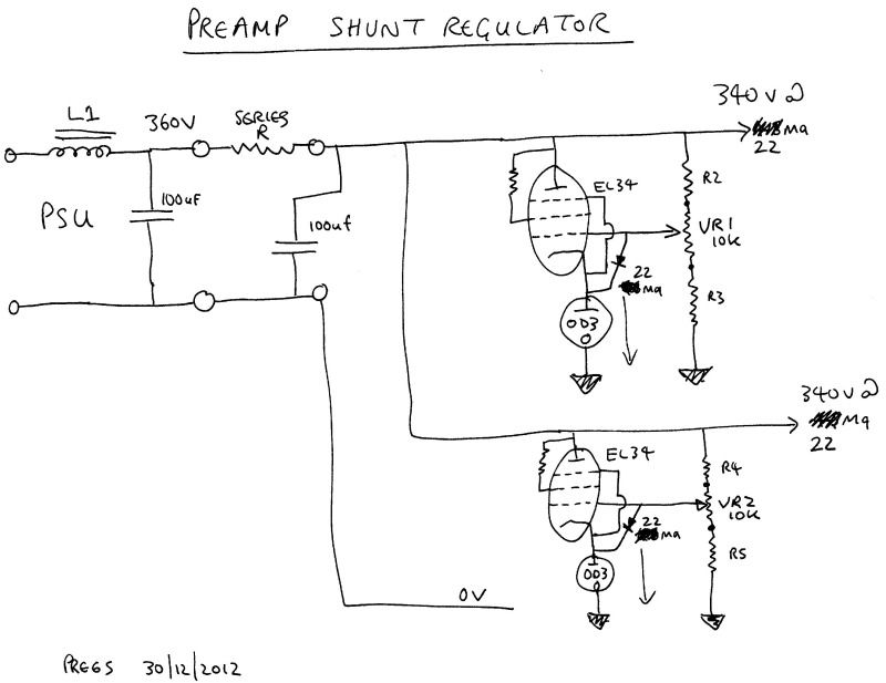
My current pre amp (2A3) transformer originally powered a 300b SET amp, so I think it's capable of supplying 88ma without drama. Now, as there are two 350v secs I could go dual mono from the transformer onwards, or, and this is perhaps easier to engineer, use the existing PSU rectifier, E-choke and first choke then split into two and have the second choke and series resistor before the twin regulators.

Would this be sufficient to stop the regulators being in parallel ?

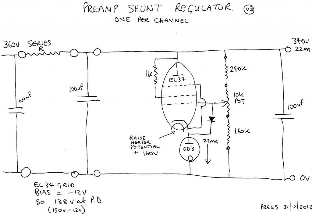
Each EL34 would be passing 22ma and in the event of no load 44ma. The OD3 is rated at 40ma so if things go bosoms up it's only just over it's limit.

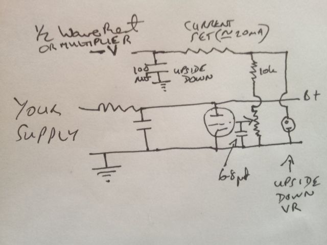
Another question, if the regulated PSU is designed for 22ma what happens if the supply draws a bit more, say (for example) 30ma ?
The only thing necessary for the triumph of evil is for good men to do nothing.

Edmund Burke

G-Popz THE easy listening connoisseur. (Philip)
User avatar
Nick
Site Admin
Posts: 15752
Joined: Sun May 06, 2007 10:20 am
Location: West Yorkshire

#14

Post by Nick »

Just split befor ethe series R, use two series R's and it will be fine.

I am trying to decide if the 100uf after the series R is a good or bad idea.
Whenever an honest man discovers that he's mistaken, he will either cease to be mistaken or he will cease to be honest.
User avatar
pre65
Amstrad Tower of Power
Posts: 21400
Joined: Wed Aug 22, 2007 11:13 pm
Location: North Essex/Suffolk border.

#15

Post by pre65 »

So Teacher, have I understood the lessons ? :wink:

Image
The only thing necessary for the triumph of evil is for good men to do nothing.

Edmund Burke

G-Popz THE easy listening connoisseur. (Philip)
Post Reply