I've been playing with DHT called a TZ40. I've been experimenting with biasing it in A2. I've used a variable HT supply AND a separate bench supply to provide the +ve grid bias so everything is adjustable 'on the fly' as it were.
I've noticed that the more I take the gid +ve the more grid current starts flowing. Is this because the grid in effect becomes more like an anode the further I ramp up the bias voltage? It's attracting more of the current flowing between the Cathode and 'proper' Anode yes?
DTB
A2 experiments.
-
Dave the bass

- Amstrad Tower of Power
- Posts: 12276
- Joined: Tue May 22, 2007 4:36 pm
- Location: NW Kent, Darn Sarf innit.
-
Mike H

- Amstrad Tower of Power
- Posts: 20189
- Joined: Sat Oct 04, 2008 5:38 pm
- Location: The Fens
- Contact:
#2
I believe so yes, the grid and cathode become like a diode.
This has to be thought about in like LTspice models, ergo all mine have a diode and a series resistance in the 'grid' pin. Otherwise the model will assume it keeps working the same if the grid goes positive, which of course it won't.
The 'useful' aspect of this is clipping of the signal when the grid goes positive, which is what happens unless the source can drive it (usually not, unless you've deliberately taken that into account), ergo is a more realistic behaviour.
The grid current does increase as the positive Voltage increases, and if it were like a proper diode behaviour the increase would be exponential. By which I mean not linear relative to the Volts ..
So what you're seeing is 'normal'
HTH
"No matter how fast light travels it finds that the darkness has always got there first, and is waiting for it."
#3
yes, as mike said, the moment the grid is +ve WRT the cathode, electrons can flow from the cathode to the grid. Just as they do in g2 of a pentode, for that matter.
Whenever an honest man discovers that he's mistaken, he will either cease to be mistaken or he will cease to be honest.
-
Paul Barker

- Social Sevices have been notified
- Posts: 8997
- Joined: Mon May 21, 2007 9:42 pm
#4
double post from a mobile phone.
Last edited by Paul Barker on Wed May 09, 2012 7:55 am, edited 1 time in total.
"Two things are infinite, the universe and human stupidity, and I am not yet completely sure about the universe." – Albert Einstein
-
Paul Barker
- Social Sevices have been notified
- Posts: 8997
- Joined: Mon May 21, 2007 9:42 pm
#5
When you look at grid current curves you see the exponential result.
Which is boosted as anode voltage reduces.
So your maximum power is limited at low anode voltages .
But it sounds good non the less, driven by a powerful low impedance source right up to this grid current exponential lift off.
I remember reading the reason for the effect towards low anode voltage in one of the data sheets but can;t remember which one.
But it is something to the effect that the realtive voltages of anode and grid pincer towards each other which speeds up the rate of grid current rise. this is a greater effect than the downturn of the anode characteristic curves which occur slightly later. (The knee we talk of in pentode curves, in a high mu transmitting valve it also exists as the curves look similar) The grid current effect happens sooner and becomes the limitation of power.
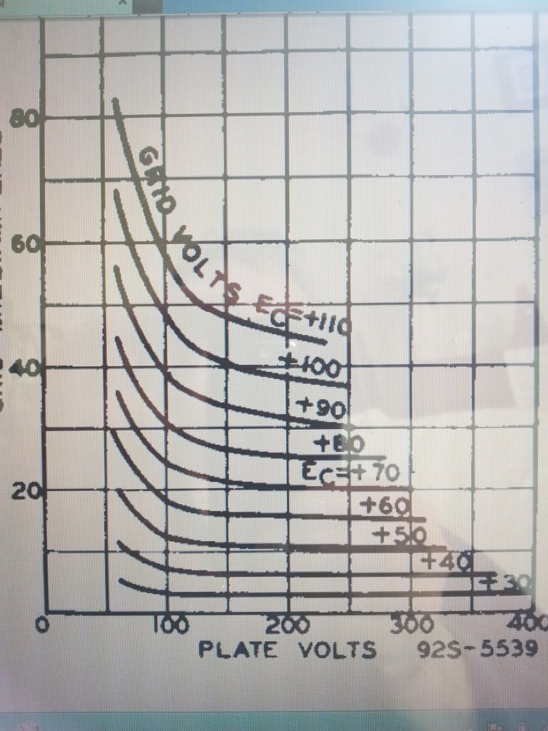
As you can see from the 801a grid current curves pictured for you, the practical excursion of voltage swing across the characteristic curve loadline needs to be considered to run out of steam at 100 anode volts, therefore the asymetrical high voltage swing will only go as far as the same opposite grid voltage swing (equidistant from quiescent grid voltage) to remain linear, dependent on the current the driver can source, and the effect on drive voltage by said current.
So practical class A2 power output expectations need to take this effect into account.
I don't think Mikes diode will work at this knee where the effect is amplified by the relative anode voltage to grid voltage effect. So Spice may imply more power output than is actual.
Even if you use a mosfet to source the grid current from alow impedance (and so build a hybrid amp YUK!) your gird dissipation rapidly limits you. If you make your driver too capable you may see your grid burn up. On the above curves you would have to draw a maximum grid dissipation curve before designing the most bang tidy drive stage.
what you have done Dave is built a jig with which you could draw these curves for any valve and then decide it's practical limits. So will benefit from the addage "the one with an experience is never at the mercy of the one with an argument".
It is great when we actually experience these things for ourselves.
Sameways when we experience the resultant sound. I remember when I never knew the "argument" that A2 is no good for audio proliferated by those without the experience but always ready to begin an argument, I just weant at it with the SV811.10 in an experiential fashion, I found it blew away the 300b and began an argument that hasn't petered out yet.
But my experience is what nourishes me not the argument.
Which is boosted as anode voltage reduces.
So your maximum power is limited at low anode voltages .
But it sounds good non the less, driven by a powerful low impedance source right up to this grid current exponential lift off.
I remember reading the reason for the effect towards low anode voltage in one of the data sheets but can;t remember which one.
But it is something to the effect that the realtive voltages of anode and grid pincer towards each other which speeds up the rate of grid current rise. this is a greater effect than the downturn of the anode characteristic curves which occur slightly later. (The knee we talk of in pentode curves, in a high mu transmitting valve it also exists as the curves look similar) The grid current effect happens sooner and becomes the limitation of power.
As you can see from the 801a grid current curves pictured for you, the practical excursion of voltage swing across the characteristic curve loadline needs to be considered to run out of steam at 100 anode volts, therefore the asymetrical high voltage swing will only go as far as the same opposite grid voltage swing (equidistant from quiescent grid voltage) to remain linear, dependent on the current the driver can source, and the effect on drive voltage by said current.
So practical class A2 power output expectations need to take this effect into account.
I don't think Mikes diode will work at this knee where the effect is amplified by the relative anode voltage to grid voltage effect. So Spice may imply more power output than is actual.
Even if you use a mosfet to source the grid current from alow impedance (and so build a hybrid amp YUK!) your gird dissipation rapidly limits you. If you make your driver too capable you may see your grid burn up. On the above curves you would have to draw a maximum grid dissipation curve before designing the most bang tidy drive stage.
what you have done Dave is built a jig with which you could draw these curves for any valve and then decide it's practical limits. So will benefit from the addage "the one with an experience is never at the mercy of the one with an argument".
It is great when we actually experience these things for ourselves.
Sameways when we experience the resultant sound. I remember when I never knew the "argument" that A2 is no good for audio proliferated by those without the experience but always ready to begin an argument, I just weant at it with the SV811.10 in an experiential fashion, I found it blew away the 300b and began an argument that hasn't petered out yet.
But my experience is what nourishes me not the argument.
Last edited by Paul Barker on Wed May 09, 2012 8:16 am, edited 1 time in total.
"Two things are infinite, the universe and human stupidity, and I am not yet completely sure about the universe." – Albert Einstein
-
Dave the bass
- Amstrad Tower of Power
- Posts: 12276
- Joined: Tue May 22, 2007 4:36 pm
- Location: NW Kent, Darn Sarf innit.
#6
Ta for the explanations Gents. I've never played in A2 before.
I'm driving the TZ40 from an old project which is a simple 6DN7 amp. The 2nd 'beefy' triode I'm feeding into one of our-Mikes Danbury Interstage TX's that I've wired for 2:1 step down which (I think) gives me low Z current drive into the grid of the TZ40 which can sit at anything between 0V and 350V (!) depending on how I set up all the bench supplies.
Its fun.
DTB
"The fat bourgeois and his doppelganger"
-
Paul Barker
- Social Sevices have been notified
- Posts: 8997
- Joined: Mon May 21, 2007 9:42 pm
#7
Yes that is one way to go about it.
I am sure you are aware that if you connect the secondary one way round as your grid draws current the current has the opposite dc effect to the quiescent primary current (with respect to core saturation), and if you connect it the other way round it makes the dc current worse. So you have to experiement with connections.
BUT sadly with all transformers there is one way round for better trebble and one way round is more dull (due to leakage inductance worstening one way round than the other which has to be tried by experimentation). It may be that the two connections are opposed to each other, or it may be not. You may be lucky or may not hear a top end roll off anyway.
You can shunt a cheap transformer with a small cap to extend the HF response.
I imagine the secondary would want low dc resistance as the pull down of voltage as current increases will materially affect the drive.
As many have found the output transformer man's up to the job, but your limit then is your voltage swing.
"Two things are infinite, the universe and human stupidity, and I am not yet completely sure about the universe." – Albert Einstein
-
Paul Barker
- Social Sevices have been notified
- Posts: 8997
- Joined: Mon May 21, 2007 9:42 pm
#8
these DA41 (closest equivalent data is available for) anode characteristic curves demonstrate the pronounced Knee. So the practical lowest anode voltage is quite high. they don't show grid curves which we can use, but be sure the upturn in grid current will precede the downward turning of the anode characteristic curves. So the final expent of the maximum power will be brought to a close rapidly.
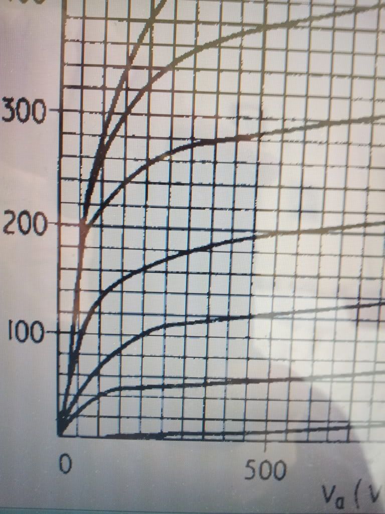
At a glance the lowest practical anode voltage (for acceptable distortion) is 250 volts.
there are better audio devices.
At a glance the lowest practical anode voltage (for acceptable distortion) is 250 volts.
there are better audio devices.
"Two things are infinite, the universe and human stupidity, and I am not yet completely sure about the universe." – Albert Einstein
-
Dave the bass
- Amstrad Tower of Power
- Posts: 12276
- Joined: Tue May 22, 2007 4:36 pm
- Location: NW Kent, Darn Sarf innit.
#9
Thanks for the intense answers our-Paul. My brain is melting!
Aye, I see what you mean about the Grid curve resembling the anode curve of a pentode. I think I'm actually experimenting further than my theoretical understanding actually goes but it's a sure fire way for me to learn, even if I blow things up.
Re- Interstage round the wrong way, yep, been there, dun that. I built a 6C45-> IT -> 2A3 and had one side of the Interstage TX wired round the wrong way and it sounded pants. Swapping two connections on the secondary around sorted it and its been in regular use since then as the main amp downstairs in the lounge. I love its sound.
I've got about 80mA of anode current flowing when the grid is about 35V +ve and the Anode voltage is 320V-ish. The 10K Hammond op TX's I'm using are only rated at 90mA so I'm keeping that in mind when experimenting.
If I can find a spare half a door to screw the whole thang to I'll lug it all up to Owston so we can blow stuff up in different County than Kent for a change
Onwards! To Audio Nirvana (banana...manyana).
DTB
"The fat bourgeois and his doppelganger"
-
Mike H
- Amstrad Tower of Power
- Posts: 20189
- Joined: Sat Oct 04, 2008 5:38 pm
- Location: The Fens
- Contact:
#10
Continuing what Paul was indicating I think it needs to be wired as below ~ i.e. grid current flow is the opposite direction to primary anode standing DC current flow.
Also, pin '1' is the start of the first winding on the former.
You can't then use the capacitor strap though as the anode end of the primary is opposite phase to the grid end of the secondary.
HTH
Also, pin '1' is the start of the first winding on the former.
You can't then use the capacitor strap though as the anode end of the primary is opposite phase to the grid end of the secondary.
HTH
- Attachments
-
- VT1399 wiring 2_1.gif (3.87 KiB) Viewed 7602 times
"No matter how fast light travels it finds that the darkness has always got there first, and is waiting for it."
-
pre65

- Amstrad Tower of Power
- Posts: 21400
- Joined: Wed Aug 22, 2007 11:13 pm
- Location: North Essex/Suffolk border.
#11
Thanks for the diagram Mike, that will assist me as well.
The only thing necessary for the triumph of evil is for good men to do nothing.
Edmund Burke
G-Popz THE easy listening connoisseur. (Philip)
Edmund Burke
G-Popz THE easy listening connoisseur. (Philip)
-
Dave the bass
- Amstrad Tower of Power
- Posts: 12276
- Joined: Tue May 22, 2007 4:36 pm
- Location: NW Kent, Darn Sarf innit.
#12
Ta Mike, I'll have a look and see how I've arranged the windings in a mo. I copied what ever was on the sheet that came with the Danglebury TX's BTW.
I've just been musing different ways to get the grid +ve. Howsabout rechargeable 9v batts in series with the secondary of the IT. The small current flowing out the grid might even charge them.
DTB
I've just been musing different ways to get the grid +ve. Howsabout rechargeable 9v batts in series with the secondary of the IT. The small current flowing out the grid might even charge them.
DTB
"The fat bourgeois and his doppelganger"
-
Mike H
- Amstrad Tower of Power
- Posts: 20189
- Joined: Sat Oct 04, 2008 5:38 pm
- Location: The Fens
- Contact:
#13
Except it's not a current source, it'll be a current drain.
The batteries will be discharged through the grid / cathode connection.
The batteries will be discharged through the grid / cathode connection.
"No matter how fast light travels it finds that the darkness has always got there first, and is waiting for it."
-
Dave the bass
- Amstrad Tower of Power
- Posts: 12276
- Joined: Tue May 22, 2007 4:36 pm
- Location: NW Kent, Darn Sarf innit.
-
Paul Barker
- Social Sevices have been notified
- Posts: 8997
- Joined: Mon May 21, 2007 9:42 pm
#15
direct couple best way to bias it.
"Two things are infinite, the universe and human stupidity, and I am not yet completely sure about the universe." – Albert Einstein