Amp initial testing.

We all start somewhere
User avatar
pre65
Amstrad Tower of Power
Posts: 21400
Joined: Wed Aug 22, 2007 11:13 pm
Location: North Essex/Suffolk border.

#1 Amp initial testing.

Post by pre65 »

Hi-i thought the time had come to start testing the PT15 amp.

So i wired the variac up to an IEC lead,and with no valves in position,and the rectifier transformer switched off i plugged in the mains and started to increase the voltage.

Within a few seconds the variac was buzzing and smoke was issuing forth.

Now the variac wont vary,gives 240v all the time,and taking the lid off reveals a black segment !

Now i have tested the power supply end of the amp with my DMM and i can find no shorts to earth.

So what now ?

Yes i know i should have used a fuse somewhere. :cry:
The only thing necessary for the triumph of evil is for good men to do nothing.

Edmund Burke

G-Popz THE easy listening connoisseur. (Philip)
Andrew
Eternally single
Posts: 4206
Joined: Thu May 24, 2007 2:18 pm

#2

Post by Andrew »

Philip, you must have a short, did you say the HT was off? So it must be the heaters.

The variac sounds kaput, sorry.

cheers,

-- Andrew
User avatar
Nick
Site Admin
Posts: 15759
Joined: Sun May 06, 2007 10:20 am
Location: West Yorkshire

#3

Post by Nick »

How was the variac wired?
Whenever an honest man discovers that he's mistaken, he will either cease to be mistaken or he will cease to be honest.
User avatar
pre65
Amstrad Tower of Power
Posts: 21400
Joined: Wed Aug 22, 2007 11:13 pm
Location: North Essex/Suffolk border.

#4

Post by pre65 »

Hi-the variac was wired as per the instructions to give 240V on max deflection (270V was optional).The variac has been quite happy providing 100v for the DD turntable.

Taking the wiring apart and doing some measuring i find that both main toroids seem to have no resistance on both 6.3v windings !

Does that seem right ?

These are the same 360-0-360 that DTB got,from USA.
The only thing necessary for the triumph of evil is for good men to do nothing.

Edmund Burke

G-Popz THE easy listening connoisseur. (Philip)
User avatar
Nick
Site Admin
Posts: 15759
Joined: Sun May 06, 2007 10:20 am
Location: West Yorkshire

#5

Post by Nick »

I would expect very little resistance, not zero, but it does depend on how accurate your meter is at low resistance readings.
Whenever an honest man discovers that he's mistaken, he will either cease to be mistaken or he will cease to be honest.
User avatar
pre65
Amstrad Tower of Power
Posts: 21400
Joined: Wed Aug 22, 2007 11:13 pm
Location: North Essex/Suffolk border.

#6

Post by pre65 »

Hi-on its lowest setting,with clip leads connected together i get between 0.3 and 0.4 ohms.

When i test the 6.3v windings i get the same figure.(on all 4 windings)
The only thing necessary for the triumph of evil is for good men to do nothing.

Edmund Burke

G-Popz THE easy listening connoisseur. (Philip)
User avatar
Dave the bass
Amstrad Tower of Power
Posts: 12276
Joined: Tue May 22, 2007 4:36 pm
Location: NW Kent, Darn Sarf innit.

#7

Post by Dave the bass »

Philip, Just an idea ... have you got the 6.3 Volt windings paralleled? Maybe they're out of phase in which case the secondary will appear a short to the variac and the primary of the TX.

DTB
"The fat bourgeois and his doppelganger"
User avatar
pre65
Amstrad Tower of Power
Posts: 21400
Joined: Wed Aug 22, 2007 11:13 pm
Location: North Essex/Suffolk border.

#8

Post by pre65 »

Hi Dave-i did have the 6.3V windings combined,two blues together,two greens together !

I will try it again in the morning with one pair taped up.

Never thought about phase,normally when you connect secondaries in parallel you just get the same voltage but double current !


We live and learn,dont we.
The only thing necessary for the triumph of evil is for good men to do nothing.

Edmund Burke

G-Popz THE easy listening connoisseur. (Philip)
User avatar
Dave the bass
Amstrad Tower of Power
Posts: 12276
Joined: Tue May 22, 2007 4:36 pm
Location: NW Kent, Darn Sarf innit.

#9

Post by Dave the bass »

Annuver idea, You've got the primary connected up right yes? ( Don't mean this to sound teaching a horse to suck grandmas or whatever the saying is.)

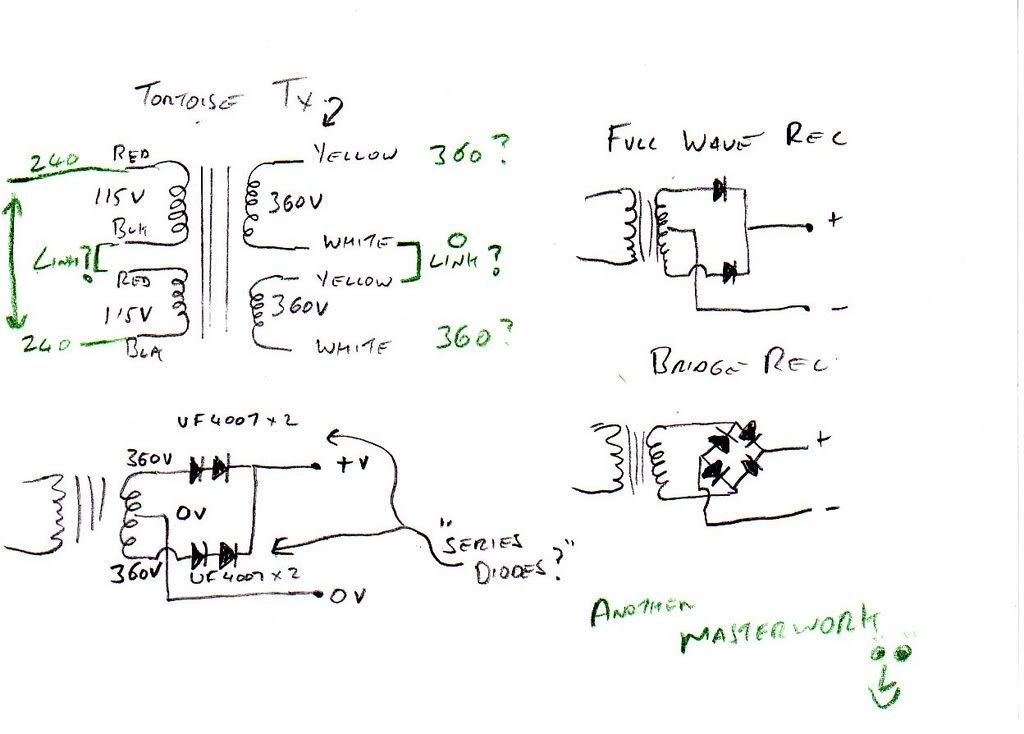
The 2x115V taps are in series yes? the top left hand picture in my scribbles pic when i was having a blonde moment.

Image

Might be worth just powering up the TX on it's own just in case it's faulty? Just power up the 2 pri#s in series and confirm that with the 360-0-360 taps are still OK and the 2 SEPERATED 6.3 heaters taps are still OK as a precaution then at least we know if the TX is ok before going any further.

HTH

DTB
"The fat bourgeois and his doppelganger"
User avatar
pre65
Amstrad Tower of Power
Posts: 21400
Joined: Wed Aug 22, 2007 11:13 pm
Location: North Essex/Suffolk border.

#10

Post by pre65 »

Hi Dave-i have wired them up as per the diagram.

Never assume anything when your dealing with me. :oops:
Attachments
Input board 002.jpg
Input board 002.jpg (67.53 KiB) Viewed 10751 times
The only thing necessary for the triumph of evil is for good men to do nothing.

Edmund Burke

G-Popz THE easy listening connoisseur. (Philip)
User avatar
Nick
Site Admin
Posts: 15759
Joined: Sun May 06, 2007 10:20 am
Location: West Yorkshire

#11

Post by Nick »

A useful thing to have in cases like this is a 40w light bulb in a holder on a bit of MDF, wire the bulb so its in series with the amp supply, that way, you can see how much current its trying to pull, if the bulb lights to normal brightness, there is probably a short somewhere.
Whenever an honest man discovers that he's mistaken, he will either cease to be mistaken or he will cease to be honest.
User avatar
pre65
Amstrad Tower of Power
Posts: 21400
Joined: Wed Aug 22, 2007 11:13 pm
Location: North Essex/Suffolk border.

#12

Post by pre65 »

Hi-i have disconnected all non necessary wiring.

Mains 3 core goes to IEC socket on the front panel.

Earth wire goes to earth pin on distribution board.

Live and neutral go to a DPST mains switch and then to the live and neutral pin on the distribution board.

The primary windings have one red,and one black wire (should it matter which pair ?) connected together on a separate pin.The other red and black wire go to the live pin (red) and neutral pin (black).

The same logic applies to the 360 secondary windings.One white and one yellow to a separate pin as the 0V connection and the remaining white and yellow to separate pins.

Now with the 6.3V windings un connected and the on/off switch in the off position 240v is measured on the IEC connector terminals.

But turn the switch on and the variac (its sort of come back to life)starts smoking almost immediately.

Surely i cant have two dud transformers ?

Somehow i feel i have done something really silly,but WOT ?
The only thing necessary for the triumph of evil is for good men to do nothing.

Edmund Burke

G-Popz THE easy listening connoisseur. (Philip)
User avatar
Nick
Site Admin
Posts: 15759
Joined: Sun May 06, 2007 10:20 am
Location: West Yorkshire

#13

Post by Nick »

There is nothing unexpected shorted underneth the insulating board is there?

What is the resistance between the line and neutral on the IEC (no mains connected) with the switch on, and whats the resistance between live and neutral and earth?

You haven't got neutral going to earth (it shoudn't), and live and neutral swapped somewhere?
Whenever an honest man discovers that he's mistaken, he will either cease to be mistaken or he will cease to be honest.
User avatar
Cressy Snr
Amstrad Tower of Power
Posts: 10582
Joined: Wed May 30, 2007 12:25 am
Location: South Yorks.

#14

Post by Cressy Snr »

Hi Philip

If you are using a double pole single toggle switch are you sure you haven't connected the mains so that when you throw the switch you are not actually putting a dead short across the live and neutral on the mains side, thereby bypassing the amp altogether?

If you have no fuse then the resulting short will draw a massive current which will cause the variac to burn up.

That's why I prefer single pole switches with just the live being switched. It avoids this sort of thing happening. with a single pole, if you have inadvertently shorted the liveto itself, then the equipment will merely fail to power up rather than do any damage.

Steve

Steve
User avatar
Nick
Site Admin
Posts: 15759
Joined: Sun May 06, 2007 10:20 am
Location: West Yorkshire

#15

Post by Nick »

That's why I prefer single pole switches with just the live being switched.
Yep, thats a good thing to check.

Also, I would check that the yellow and white you have commoned, are from different windings. Though Steves idea sounds likely, I would have expected unhappy noises from the TX's if there was a secondary short.

I must admit, as I tend not to use off/on switches I don't think about that sort of a problem. I don't think any extra safty is gained by the use of DPDT switches unless the L and N are swapped.
Whenever an honest man discovers that he's mistaken, he will either cease to be mistaken or he will cease to be honest.
Post Reply