Paul,
That is quality even to my untrained eye. I'm taking it that the signal to the series pass valve grid, especially in the absence of a shunt regulator, needs to be as clean as possible hence this undermines the whole design and the reason you have a separate dedicated 'supply'.
I obviously have some way to go but to get this project off the ground, compared to the link I provided, and also taking some inspiration from your reference circuit I was going to:
1. Change the glow tube with a 300V stack of zener diodes
2. Put a 100k pot across the zeners in series with a lower 100k resistor.
3. Add a cap between the grid connection and 0V
I do have a few spare OB2 tubes as spares for my AN DAC. I take it from the code that they are 108V each so could rig up 3 with a 10M45 CCS. Is this worth the initial effort if I start with a capacitor power supply and solid state rectification?
So looking at the 6AS7 datasheet, if for the 6BL7 driver I need a 300V and 60mA load, if I allow for a minimum 50V across the regulator, Vgk needs to be around -15V so the grid will be at 285V???
For the IRF820 option, I could get a +/- 150V swing at 50mA each with a supply voltage of +/- 185V. But the 6AS7 would see 165V and 13W only gives me 78mA so would need to drop the supply voltage to the series pass valve down below 315V.
Variable split power supply
-
little eddy
- Old Hand
- Posts: 693
- Joined: Sun Nov 09, 2008 2:06 pm
- Location: Manchester
#16
TD-125/RB250/MC25FL & 'Snail' phono, NAS/SBT with CS4398 DAC, 41MP pre & MoFo Power, still messing with OBs.
-
Paul Barker

- Social Sevices have been notified
- Posts: 8989
- Joined: Mon May 21, 2007 9:42 pm
#17
For the mosfet option consume some voltage with choke input? You're
maths is excellent and your understanding too.
maths is excellent and your understanding too.
"Two things are infinite, the universe and human stupidity, and I am not yet completely sure about the universe." – Albert Einstein
-
little eddy
- Old Hand
- Posts: 693
- Joined: Sun Nov 09, 2008 2:06 pm
- Location: Manchester
#18
Paul,Paul Barker wrote:This is my latest "ideal" power supply.
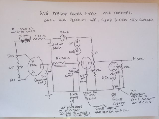
Is the regulation there because you haven't yet finalised your load voltage or current? Or is it the best compromise because to want to regulate rather than adjust the voltage? Or do you believe this is better sounding than a simple choke filter?
TD-125/RB250/MC25FL & 'Snail' phono, NAS/SBT with CS4398 DAC, 41MP pre & MoFo Power, still messing with OBs.
-
Paul Barker
- Social Sevices have been notified
- Posts: 8989
- Joined: Mon May 21, 2007 9:42 pm
#19
Good questions.
I can only answer with nothing but my experience and my opinions formed by those experiences may not be the opinions of others. They are not stated intentionally pedantically, they are stated factually. That is what are the clear facts of my experience.
1/ Simple choke input sounds great and always improves the bass of a SE amp. but has no other benefit I have heard. But since SE amps struggle with bass the strength of choke input is a vast improvement. Felt most greatly in the 300b but required in all Se amps in my view.
2/ The shunt regulation sounds great always improves the bass of a SE amp and has benefits across the spectrum.
In my view the combination should be better still. I don't have an issue if people don't choke input when they are shunt regulating, but in my work I don't see why shunt regulation should eliminate the benefits of choke input. If you observe the voltage current graph of either it looks very much the same. Neither is a straight horizontal line. therefore each is additive and in combination the sloap of the line will be more horisontal than with each individually. Therefore to not use choke input when shunt regulating is a compromise.
But my experience which makes me always use choke input for every project is also a hybrid of choke input combined with capacitorless power supply design, in which choke input or resistor input are the only two choices. As Steve Bench put it effectively my best power supplies are L R power supplies. Loads of chokes and resistance in series and loads of shunt current.
The last decent amp I had 801a was LR power supplied. The L was about 40h the dc resistances about 250ohm. for a while I compromised with a Black Gate. Plus two stages of 572b shunt regulation. Previously I had basically this power supply but with no Black Gate it was truly resistorless and capacitorless. I took it to the first Eggborough and demonstrated it together with various output valves. ST PX4 ST PX25 and Balloon PX25. the sound quality ascended in that order. but the power supply was the best part of the whole thing. At home I have always used such a power supply since those days. The advise I give here is usually a comptromise position and that seems extreme to most. What I do at home is completely obsessive.
So to get back on track, when I removed the black gate the sound of the 801a improved in no small step.
Right now though I do have a small amp with choke input and shunt regulation but it does have that Black Gate. That is because I wanted something small and easy to manage for the family room.
Now regarding the series reg in my diagram. I have yet to prove it by sonics, but my expectations are that it will sound good in this form. I believe the more stages of error correction are added (i.e.extra error amplifier valve) the more you will change the timing to the detrement. Maybe the series pass element will also change the timing to the detrement. What I have drawn is conceptual and electrically correct, but not endorseable, it is suggestible.
The design could be taken to the capacitorless extreme.
When I shunt regulate to the extreme of not having capacitors at all I have to basically devide the currents in three equal parts. there is a choke and then the first shunt regulator, more chokes and the second shunt regulator finally the output stage. So if the output stage takes 150mA so does the second 572b and so does the first 572b. Your transformer and diodes provide 450mA with margin so I use 500mA transformer. The first choke has to hanlde 500mA. the next choke has to handle 300mA. the voltage drops across the dc resistances have to be considered as there is so much current.
But the sound far suprasses anything else.
"Two things are infinite, the universe and human stupidity, and I am not yet completely sure about the universe." – Albert Einstein